By Jeffrey Kilburn, Global Product Marketing Manager, Logic Components, Rockwell Automation, Milwaukee, Wis.
Signal-conditioning modules should be selected and installed in a manner that preserves the small signals by minimizing ground-loop currents and common-mode noise.
Like a fuel injector in a high-performance engine, signal conditioners perform a critical, yet often under-recognized function. Signal conditioners isolate, transmit, and convert a wide range of process signals into a format that is compatible with the receiving device, such as a programmable logic controller. As the number and variety of interconnected sensors and control devices continues to grow, plant-floor engineers face increased demands to guard against the many electrical interfacing problems that can occur. Signal conditioners can help resolve these issues.
Employed wherever temperature, pressure, flow, speed or other process values are measured and controlled, signal conditioners help protect these measurements from being corrupted as they transmit the measurement data from the field where the sensors collect data to the plant control room. The latest advances in signal conditioner technology include more rugged, robust devices. These conditioners provide more functionality in smaller packages, give users greater design and integration flexibility, and help reduce cables and maintenance costs.

Analog signal conditioners convert, isolate, and amplify signals. They can convert voltage signals to standard 4 to 20 mA signals and use existing I/O. Also, they can isolate multiple field-measurement devices on a common power supply to help prevent interference that can occur due to ground loops or common-mode noise.
Practical Applications
A signal conditioner’s primary function is to isolate measurement and control signals. Such isolation prevents interference that can occur due to ground loops or common-mode noise. A ground loop occurs when more than one ground connection is made to a single control signal. In such a case, a potential difference in the Earth ground at each location can create an additional and unpredictable amount of current in the loop, which distorts the measurement. Signal conditioners break the ground loop current path and maintain the integrity of the measurement.
Often the signals from the sensors and transducers are small voltages. As such, they are susceptible to noise pickup from motors, variable speed drives, welding equipment, and general switching spikes carried by a plant’s electrical system. If there is no isolation between input and output, this common mode noise will produce unacceptable changes in the output current or voltage. Applying signal isolation will help prevent the noise from passing to the output, even when it is relatively high in magnitude.
Many industrial applications, such as oil and gas or chemical production, often require process measurement signals to be accurately transmitted over long distances. Instead of running expensive and noise-sensitive thermocouple or RTD cable to the control system, signal conditioners can isolate and convert to a high-level 4-20mA current signal that can be transmitted over standard copper conductors, which are less expensive and more noise-tolerant.
Signal conditioners also allow for the low-cost addition of an analog signal in an established process that has limited analog I/O expansion capability. Rather than buying another I/O card, plant-floor managers can use external signal conditioning modules to convert an analog signal into a format that can be used on an open channel in an existing I/O module in their control system. Also, by sticking to one multi-channel input card type, users may be able to extend the performance of their legacy control systems and cut the cost of stocking spares for each module type. Additionally, many small PLCs only offer a 0-10Vdc analog input on the base unit. Signal conditioners can be used to convert the more common 4-20mA analog signals into a 0-10Vdc signal, allowing for cost-effective expansions to a system that uses small programmable controllers.
Another core function of signal conditioners is signal splitting in which the conditioner takes one signal input and provides two identical outputs. All inputs, outputs, and power are isolated from one another. The splitter approach allows managers to disconnect either control system for maintenance without affecting the signal going to the other system. Signal splitting is a common tactic in applications where the user needs to monitor the input from a field transmitter at two locations simultaneously. Here, a dual-output signal conditioner takes the input from one transmitter and sends two identical isolated outputs to two receiving devices for monitoring, recording, and control. Users also employ this technique for isolating validated systems from non-validated systems in the bio-pharmaceutical market.

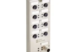
Isolating Signal Conditioner for analog current loops: input loop powered.
Typical symptoms that indicate the need for signal conditioning include:
• A transmitter or some other piece of equipment works perfectly well on the test bench but will not work when
installed in the plant.
• The readings received from a transmitter in the field change noticeably when another seemingly unrelated piece of equipment is connected to the system.
• Two pieces of equipment have different grounding requirements and cannot be interconnected directly.
• The measurement into a receiving system varies unexpectedly when nearby electrical devices are operated.

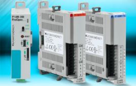
Isolating Signal Conditioner for analog current loops: auxiliary powered.
Selection Criteria
Even with the wide variety of analog I/O available in today’s modern process control systems, signal conditioners continue to deliver valuable problem-solving capabilities. Modules are available for most types of analog signals, but selection criteria beyond signal types must first be considered. Users must be careful to match the response time to the application, and make sure the signal conditioner can handle the sensor load (impedance).
Signal conditioners with two-way isolation electrically separate the input and output signals from each other and decouple the measuring circuits. This eliminates potential differences caused by long-line lengths and common reference points. The electrical separation also protects against irreparable damage caused by over-voltages.
Signal conditioners with three-way isolation also separate the supply voltage from the input and output circuits and enable the analog circuit to operate with one operating voltage. Signal conditioners with passive isolation, such as Input Loop powered or Output Loop powered devices offer an additional advantage: They do not require an additional power supply. The input or output circuit can provide the power supply to the signal conditioner.

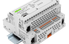
Converting Signal Conditioner with configurable analog input and output: auxiliary powered.
Stocking I/O cards for different sensor applications can be expensive. Fortunately, universal signal conditioners are available in one configurable module that can handle inputs from any thermocouple, RTD or potentiometer, as well as a range of millivolts, resistance, frequency, current, and voltage. These help users minimize their electronics inventory while serving as a major functional element of the I/O interface to the PLC.
Accurate signals are integral for keeping plant operations running efficiently and without incident. Signal conditioners are a cost-effective tool for safeguarding signals and maintaining uptime. A variety of signal conditioner models and capabilities can seamlessly fit the particular needs of an existing control system. Though often invisible, signal conditioners provide a critical link for analog signal transmission in new and existing installations.
Discuss this on the Engineering Exchange:
Rockwell Automation
http://www.rockwellautomation.com
::Design World::
Filed Under: Signal analyzers, TEST & MEASUREMENT

Tell Us What You Think!