When an electric motor fails to start, runs intermittently, runs hot, or continually trips its overcurrent device, there my be a variety of causes. Sometimes the trouble lies within the power supply, including branch circuit conductors or motor controller. Another possibility is that the driven load is jammed, binding or mismatched. If the motor itself has developed a fault, the fault may be a burnt wire or connection, a winding failure including insulation deterioration, or a deteriorating bearing.
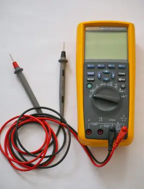
A number of diagnostic tools – a clamp-on ammeter, temperature sensor, Megger, or oscilloscope – may help illuminate the problem. Preliminary (often definitive) tests generally take place using the ubiquitous multimeter. This tester is capable of providing diagnostic information for all sorts of motors.
If the motor is completely unresponsive, no ac humming or false starts, take a reading at the motor terminals. If there is no voltage or reduced voltage, work back upstream. Take readings at accessible points including disconnect(s), the motor controller, any fuses or junction boxes, and so on, back to the over-current device output at the entrance panel. What you are looking for is essentially the same voltage level as measured at the entrance panel main breaker.
When there is no electrical load, the same voltage should appear at both ends of the branch circuit conductors. When the circuit electrical load is close to the circuit capacity, the voltage drop should not exceed 3% for optimum motor efficiency. In a three-phase hookup, all legs should have substantially equal voltage readings, with no dropped phase. If these readings vary by a few volts, it may be possible to equalize them by rolling the connections, taking care not to reverse rotation. The idea is to match supply voltages and load impedances so as to balance the three legs.
If the electrical supply is satisfactory, examine the motor itself. If possible, disengage the load. This may restore motor operation. With power disconnected and locked out, attempt to turn the motor by hand. In all but the largest motors the shaft should turn freely. If not, there is an obstruction inside or a seized bearing. Fairly new bearings are prone to seizure because the tolerances are tighter. This is especially true if there is ambient moisture or the motor has been unused for a while. Often good operation can be restored by oiling front and rear bearings without disassembling the motor.
If the shaft turns freely, set the multimeter to its ohms function. The windings (all three in a three-phase motor) should read low but not zero ohms. The smaller the motor, the higher this reading will be, but it should not be open. It will usually be low enough (under 30 Ω) for the audible continuity indicator to sound.
For proper motor operation, all windings must have megohm readings to ground, i.e. to the motor enclosure. If a winding is grounded out, the winding insulation is broken down or the armature is touching the stator, unless there is a possibility of a loose or chafing wire inside.
Small universal motors, as for portable electric drills, may contain extensive circuitry including a switch and brushes. In the ohmmeter mode, connect the meter to the plug and monitor the resistance as you wiggle the cord where it enters the enclosure. Move the switch from side to side and, with a trigger switch taped so it remains on, press on the brushes and turn the commutator by hand. Any fluctuation in the digital readout may point to a defect. Often a new set of brushes is what is needed to restore operation.
Amperage readings are useful in all kinds of electronic and electrical work. With a voltage reading, you know the electrical energy available at the terminals, but you don’t know how much current flows. Multimeters always have a current function, but there are two problems with it. One is that the circuit under investigation must be cut open (and later restored) to put the instrument in series with the load. The other difficulty is that the multimeter is not capable of handling the amount of current present in even a small motor. All the current would have to flow through the meter, instantly burning the probe leads if not destroying the entire instrument.
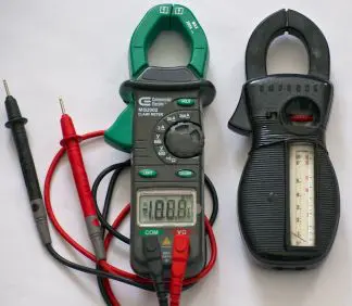
An excellent tool for motor current measurement is the clamp-on ammeter (trade name Amprobe). It circumvents such difficulties by measuring the magnetic field associated with that current, displaying the result in a digital or analog readout calibrated in amperes.
The clamp-on ammeter is absolutely user friendly. Just open the spring-loaded jaws, insert either the hot or neutral conductor, then release the jaws. The wire need not be centered in the opening and it is OK if it passes through at an angle. However, an entire cable containing hot and neutral conductors cannot be measured this way. That is because the electrical current flowing through the two wires travels in opposite directions so the two magnetic fields cancel out. Consequently, it is not possible to measure the current in a power cord, as is often desired. To deal with this situation, make up a splitter. This is a short extension cord of adequate rating with about six inches of jacket removed so that one of the conductors can be separated and measured.
Digital and legacy analog clamp-on ammeters work well and are capable of measuring up to 200 A, which is adequate for most motor work.
The basic procedure is to measure the start-up and running current for any motor while it is connected to a load. Compare the reading to documented or nameplate specifications. As motors age, the current drawn generally rises because winding insulation resistance drops. Excess current causes heat, which must be dissipated. Insulation degradation accelerates until there’s an avalanche event, causing motor burn out.
The clamp-on ammeter reading will tell you where you stand on this continuum. In an industrial facility, as part of routine motor maintenance, periodic current readings can be taken and put into a log posted nearby so damaging trends can be spotted in advance to avoid expensive downtime.
The post Basic motor testing with multimeters and ammeters appeared first on Test & Measurement Tips.
![]()
Filed Under: Test & Measurement Tips