By Steve Meyer, Contributing Editor
Mechatronic challenges come in all sizes, from giant 450-ft wind turbines to tiny piezoelectric actuators. Among the more unique and challenging applications is the technology needed to test gun sights.
The military has a small challenge for you. Create a simulation that applies forces comparable to gunfire. Doesn’t sound too bad, does it? Well, here are some specs to consider: Bolt actions must be in excess of 100 in./sec. The peak acceleration is more than 3000 Gs. And this all has to happen at a rate comparable to automatic weapon fire—which would be about 300 rounds per minute.
Military agencies spend a lot of time and money testing equipment that will be used in the field. No one wants to be in the middle of armed conflict, but if you have to be there, you want to be sure that all your gear works the way it’s supposed to.
Sights for handguns and rifles have evolved in recent years from relatively simple ground glass optics, laser targeting systems, to today’s solid state CCD and thermal imagers. Because the dominant technologies are silicon-based electronics, it becomes necessary to subject the electronics package to the unique forces that occur in actual gunfire. Testing electronics for shock and vibration is not new, but testing protocols for electronics mounted on pistols and rifles present a unique set of problems.
Weapon shock data
The actual forces acting on a rifle are not very well documented. It’s a lot harder to simulate something when the data describing the event are limited. The engineers at Ascendant Engineering Solutions decided to use multiple 3-axis accelerometers and high speed data capture to gather more accurate information about the firing of weapons—no sense making assumptions when you can get the real information. And there were some surprises.

This graph shows the energy content for a bullet being fired, the Pyrotechnic Event. The unexpected information was the significant energy in the Bolt Forward part of the cycle firing cycle.
In addition to the shock that is expected when the bullet is fired, there is a significant amount of energy opening and closing the bolt to reload the weapon. This “chambering” shock was not documented in any of the engineering literature about weapons. Since the bolt action contains higher frequency spectra than the bullet, some modification of the force requirement was necessary in order to avoid false positive results due to incomplete event models. The industry already had problems with testing weapons sights, and an improved design was needed.

The graph shows the two very different frequency distributions of the two different sources of stock.
Gun impedence
The typical approach to applying shock to a test part would be to couple the part to a rigid base.

In the case of the imaging electronics, this would be a mistake, because the sight is mounted to a rifle. The mass relationship and recoil characteristics of a soldier shouldering the weapon can be more accurately represented by a gun body of approximately two times the mass of the sight in a compliant, not rigid, framework. The difference in frequency response of the two cases for stiffness of load to base coupling would be approximately 25%. An error in this area of the system design would, again, lead to invalid testing results.

In order to qualify imaging hardware that is to be mounted on a rifle, that hardware has to be tested using live weapon fire. This is a time-consuming and expensive process, as trained specialists must take the weapon and sight and shoot hundreds of thousands of rounds of live ammo in order to verify that the sight electronics can be used in the field.
If a specific sight is required to qualify—at 100,000 rounds or more of live fire—and the cost of performing this task is $1-2 per round, hundreds of thousands of dollars will be spent to find out if a candidate sight can be used in the field. Often, testing is required periodically to ensure that a manufacturer’s product is performing consistently, which adds an ongoing feature to the need for testing. The indirect costs of maintaining a test facility and special testing capabilities for low temperature operation makes the task more difficult and expensive. For a given weapon sight, the cost of qualification testing, periodic testing and extended temperature range testing can reach annual costs of $1 million.

Large steel cable mounts provide the flex needed to represent the recoil of the weapon against the shoulder of a person holding the rifle.
Live testing of weapon sights requires actual weapon fire, where the bullet accelerations are measured in the range of 10,000 to 30,000 Gs. So if an alternative form of testing is going to be used, it must produce huge forces at high rates of speed. Full automatic live weapon fire can reach levels of 1000 rounds per minute, but existing test technology, such as drop testing or impact testing, has only been capable of testing at rates up to 8 cycles per minute and cannot accurately simulate all the forces acting on the sight being tested. This has left a gap that needed to be addressed.
Setting performance goals is a key activity in a successful engineering effort. The more detailed the goal setting, the better. In order to make a significant improvement in testing of sights, the engineers at Ascendant Engineering Solutions set out to understand the problem and created the following program goals that the system will:
• be capable of operating in all Mil-Standard temperatures -40° C to 70° C
• be portable, not requiring special infrastructure to operate
• accurately reproduce all shock forces and spectra
• simulate proper mass impedance of the gun mass to the sight being tested
• simulate the proper recoil damping of weapon being shouldered
• operate at speeds approaching full automatic rates
Navigating the technology tradeoffs
High energy density electromagnetic systems, such as rail guns and maglev roller coasters, have the energy density to duplicate the force of gunfire, but supplying power to these systems is a major engineering effort, in addition to the actuation task itself. Because one of the goals of the program was to eliminate the need for special support infrastructures, an electromagnetic solution for the “pyrotechnic event” was considered infeasible.
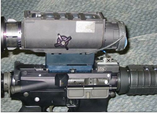
Photo of the complete system showing computer, screen, and keyboard for scale. The unit is small enough to be handled by two men and will fit through a normal door closing.
Hydraulic systems have the power density, but the viscous nature of hydraulic fluids suggests that a hydraulic system will not be capable of achieving the high cycle rates of automatic weapon fire. Since air is a fluid with very low viscosity, an all-air solution was contemplated. The high speeds that are possible with air actuators made pneumatics the lead candidate for evaluation.
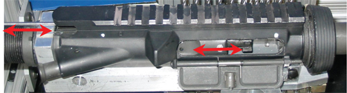
The bolt action of an M4 rifle is 4-in. of stroke length. It has to be opened and closed 5 times per second in between the impact of firing the weapon. Five cycles of open and close is 40 in. of actual travel which have to start, stop, settle, and take place in between firing impacts. Given the much higher cycle rates experienced in automatic weapon fire, the actual speeds are many times higher, making this aspect of the weapon simulator impractical for an electromagnetic solution. AES’s engineers quickly concluded that pneumatic actuation would be the most likely solution.
Muzzle impact using pneumatic cylinder to simulate pyrotechnic event.
Within a few months’ time, AES was able to set up prototype elements of the design to test the theory of making the simulator perform the bolt action and the firing impact. The results are impressive. The company was able to achieve a 300 round per minute firing rate by using common off-the-shelf pneumatic cylinders with high speed controls. NFPA standard air cylinders are the chosen solution in the Weapon Shock Simulator. Because of the low cost and simplicity of common off-the-shelf parts, the wear expected from high cycle rates is easily dealt with by replacing the cylinders at specific intervals as part of regular maintenance.
Weighing in at less than 200 lb, the simple steel frame provides the needed support and wire ropes provide the compliant coupling comparable to an actual person shouldering a weapon. The computer controlled system provides a simple graphical user interface and detailed operating software to run automated testing at 300 rounds per minute with supervisory features to shut the system down if it starts operating outside its design characteristics.

The system also operates throughout the entire temperature range (-40° C to 70° C) that the military uses for testing to ensure proper operation under all conditions. Just getting a human being to be able to test something at -40° C involves some pretty spectacular and expensive protection. Since the AES Weapon Shock Simulation system is designed to operate automatically at the full range of temperatures, manual testing by human beings in the extreme temperature ranges is not necessary.
The system operates using 110 V ac power and standard pneumatic parts for air supply. A dedicated computer is used to provide a simple Graphical User Interface based on National Instrument Labview, for setting up testing and recording event data. In addition, there are sensors and internal software that measure performance to insure proper operation. If anything goes out of design tolerance, the system automatically shuts down.

Ascendant Engineering Solutions
www.aesaustin.com
::Design World::
Filed Under: Factory automation, The Robot Report, Motion control • motor controls, Mechatronics


Tell Us What You Think!