Machine builders and end users are discovering that the use of pneumatics that integrate safety technology can enhance system reliability and extend operational life.
By Erl Campbell, Food and Beverage Key Account Manager, Aventics
The widespread use of pneumatics technology for packaging machines—to drive motion and actuate machine sequences—has garnered more interest by machine designers and end users as to how pneumatics can improve safety and safe operating functionality in their equipment.
This increased interest is due, in part, to the globalization of the packaging machine marketplace. Many major packaging OEMs are focused on building machines that can be sold into multiple markets and regions with minimal modifications.
To do so, these machines need to satisfy safety regulations—especially for European markets. In addition, machine builders and end users are also discovering that the use of pneumatics that integrates safety technology can also enhance the reliability of their systems and extend their operational life.
Regulatory developments drive pneumatics safety growth

Packaging equipment relies heavily on pneumatics for safe operating functionality.
Globally, statutory guidelines for the design and operation of machines mandate a risk assessment to identify potential hazards, minimize risks and comply with applicable health and safety requirements to protect both people and machines. The main regulatory standard that affects pneumatics technology in packaging systems is ISO 13849, which provides safety requirements and guidance on the principles for the design and integration of safety-related parts of control systems.
It’s important for machine designers to take into account all the moving parts in an axis—a pneumatic actuator or cylinder, for example—and how that motion needs to be controlled to create safety circuits that satisfy the ISO 13849 requirements. “ISO 13849 requires machine manufacturers to apply the recognized rules of good engineering practice and proven safety principles and recommends validation procedures,” said Dr. Rolf Zollner, a leading European safety risk management consultant. “One thing is frequently short-changed: Not only electric controls can be used to realize safety-related controls—pneumatics can also get the job done.”
Pneumatics-based safety functions
In short outline, a safety control circuit defined by ISO 13849 has three basic elements:
• an input, such as a sensor like a safety door, safety mat or light barrier that detects an event identified as presenting a safety hazard;
• a logic that evaluates the hazard, such as a safety PLC or safe pneumatic with pre-programmed logic to respond in a set path based on the sensor’s input;
• and an actuator, which initiates the safe reaction, such as limiting speed, reduc- ing pressure or force or initiating a safe exhaust of pneumatic pressure to stop cylinder motion and bring moving machine parts to a safe standstill.

Design engineers need to be able to selectively control how safe exhaust operates on vacuum cups, for example, where damage can occur if the vacuum is suddenly lost.
Safe pneumatic circuit design focuses on what happens to pneumatically powered machine axes and actuators when there is a loss of power and the pneumatic circuits are no longer receiving the necessary power. When power loss occurs, the pneumatics on a packaging system can be used to automatically initiate several measures to protect people and machinery, such as reducing pressure and force, safely releasing energy and guaranteeing a safe direction of travel or blocking a movement.
Safe exhaust and safe holding functions
Safe pneumatic exhaust can be illustrated by describing a typical packaging machine that incorporates pneumatic actuators. In a tray-wrapping machine for example, the transparent wrapping material unspools from a roller that is controlled by pneumatic cylinders and valve systems.
If there is a jam in the wrapping functionality, sensors at multiple points on the machine detect the jam and initiate a machine shutdown that incorporates safe exhaust. The air is safely exhausted from the pneumatics within the machine in a controlled manner, removing energy from the system and preventing any damage to the equipment; it also ensures that an operator can enter the machine enclosure and safely clear the jam.
When safe exhaust is initiated, the valves move to the basic (or default) position to depressurize the system. To ensure successful safe exhaust, there should be two safe exhaust pathways with two valves, so if one valve fails, it is backed up and safe exhaust occurs.
Typically, safe pneumatic exhaust circuits require multiple components: two valves, two sensors and an air-monitoring unit. Recently, pneumatics suppliers have been creating safe exhaust valves with sensors integrated into the units to simplify wiring and testing of the circuit.
In certain circumstances, exhausting the pneumatic system may prevent the machine from being cleared in a timely manner. In the example described above, there may be cylinders that have air trapped in them at safe exhaust (by design), but need to be moved by the operator to clear the jam.
In this situation, an alternative safety function called safe holding can be designed into the system and initiated. To move that actuator to clear the jam, it is necessary to open up the ports to that cylinder. Many pneumatic systems use manifold valves to control airflow to multiple actuators and cylinders, and the newest generation of valves incorporates features that allow operators to send a separate signal to a specific valve to open and allow the cylinder to be moved to clear the jam and restart the machine.
Safe vacuum control and safe restart
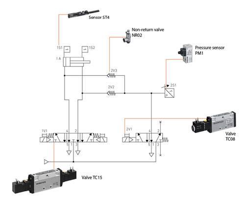
Implementing safe dual-channel exhaust with pneumatic products.
Vacuum cups and pneumatic grippers are also common actuators in many lightweight packaging applications, used to pick up items and place them in a box, bag or other container. In a situation when the machine initiates safe exhaust, machine designers and packagers don’t want the items held by these actuators to be dropped.
Design engineers need to be able to isolate and selectively control these components on the manifold—electrically and pneumatically. A pilot-operated check valve can be used to lock the cylinder and maintain the grip while the other pneumatics are de-powered. Certain pneumatic manifolds now incorporate features to have auxiliary power supplied to different sections of the manifold. In the event of a safe exhaust, a signal can be sent to keep power on to the vacuum side of the valve and reduce or drop the electrical out of the rest of the manifold.
To ensure safety in machine operation and protect against machine damage, some machine builders are also incorporating safe pressurization into their designs. Similar to a “soft start” on an axis driven by a servomotor, it uses pneumatic valving to slowly and safely bring all the pneumatics in the machine up to full pressure at machine start-up or restart; this helps protect against damaging the actuators and other equipment from abrupt starts. This can be highly useful in packaging machines with frequent changeovers for different packaging formats or materials.
Using B10 and MTTFd to select reliable pneumatics
ISO 13849 also provides a framework for establishing and documenting component reliability. Engineers have to define a required performance level (PL) in a risk assessment for a given machine function, depending on the probability of occurrence and frequency of risks, as well as the severity of possible injuries. This PL must be achieved by means of technical safety precautions.
Safe pneumatic switching processes and the reliability of the safety-relevant components contribute to these efforts. That reliability is documented using two measures: the B10 value for physical components, and Mean Time To Dangerous Failure (MTTFd) for electrical components.
In pneumatic valves, the B10 value indicates how many switching cycles it takes for 10% of components to exceed defined limits, such as switching times, leaks or switching pressure under specific conditions. Some safe exhaust valves have a B10 of 250,000; others are engineered for much higher levels of reliability, achieving B10 values up to 10 million.
MTTFd describes the mean duration in years until a dangerous system component failure. It is a statistical value for electrical/electronic components, which is identified through trials or reliability prognoses based on failure probabilities for the components.
In terms of machine safety, ISO 13849-1 only considers dangerous machine failures. These are described by B10d; the dangerous failure number is typically higher by a factor of two, since not all failures would be catastrophic and most components would only have diminished function once the B10 number is reached.
Extending machine life and value
It is up to the machine designer to select the pneumatic components for safety circuits based on the ISO guidelines for assessing the safety-related risk factors for a given machine, to satisfy the PL requirements. However, selecting pneumatic components with greater documented longevity is not just purely for safety or purely to align with evolving standards.
Safety and machine value go hand in hand: safe pneumatic components documented to provide years of reliable performance enhance operational reliability, reduce maintenance costs and increase packaging equipment uptime—all of which contribute to improved productivity and return on investment.
In addition, new sensor technology is being integrated into many pneumatic valves and other components to capture data such as cylinder stroke length and valve cycle counts. This is data that can be used for predictive maintenance and replacement programs to make doubly certain that machine and operator safety is maximized.
The ISO 13849 directive has led many top pneumatics technology companies to invest in, document and receive third-party verification of the improvements in reliable operation of their components, as well as enhance how those components can be more easily integrated into safe pneumatic circuits. For packaging machine designers and builders seeking to build globally marketable machines, this presents one more convincing reason why pneumatics remains an important and viable drive technology for their systems.
Aventics
aventics.us
Safe pneumatic features
 1. Good leakage values minimize the risk of failure. Pilot air can be controlled internally or externally: if a problem occurs, the valves switch to a defined safe state.
2. The bus coupler provides galvanic separation between logic voltage (UL) and actuator voltage (UA) in the bus coupler. This results in separating safety-related functions from other functions, thereby fulfilling ISO 13849-2 safety principles.
3. The pressure sensor module is used to safely monitor system pressures and provides reliable, fast information about pressure conditions in all relevant modes of operation.
4. The electrical supply plate provides actuator voltage to the valves, enabling independent voltage zones with any number of valves. Safety functions remain separate from other functions.
5. Pressure supply plates enable mutually independent pressure zones for customized pressure supply to different safety circuits and ensure adequate and rapid system exhaust.
6. Exhaust module: in case of an emergency stop, cylinder chambers may remain under pressure. To change the cylinder position (for maintenance or workpiece positioning) targeted system exhaust can disable the
cylinder without having to apply energy. Integrating this module in valve systems reduces sensitivity to actuator movements.
7. The pressure regulator module provides safe control of compressed air in the working lines for safe pressures and controlled cylinder movement. Many safe pneumatic functions can be supplemented by reducing pressure and force.
Filed Under: Pneumatic Tips