By Dr. Walt Pastorius, LMI Technologies, Inc., Windsor, Canada and Martin Sanden, LMI Technologies AB, Ogardesvagen, Sweden
Tire manufacturers must use highly reliable inspection systems to detect minute geometric defects and guarantee continuous production of quality and safe tires. Multiple, high-resolution sensors located in a single station scan tread and sidewall surfaces and generate imaging data that exposes the defects. The process maintains tight synchronization among all the sensors and position encoders to generate high-accuracy images.
Digital cameras record a 2D-image of the tire surface located under a scanning laser beam, and as the tire rotates, the system builds a 3D profile map. With profiling rates of 4 kHz or higher, the sensors measure accuracies to within ±50 microns at 256 points per profile.

In this demonstration, the 2D digital camera detects the path of a laser beam as it draws a line on the target block during one scan. The image on the display shows the rise and the fall of the beam as it passes from the table onto the block and down again.
Inspection challenges
In-process inspections record profiles of tire-tread extrusions. Inspection stations located near the extruder die quickly detect and repair any process deviations. A typical application may use 8 or more sensors (4 above and 4 below the conveyor) to generate high-density data across the full width of the extrusion. With differential sensing, accurate profiles can be obtained even when the extrusion location is not controlled. An encoder mounted on the conveyor line identifies the position of each profile along the extrusion.
Two cameras or sensors must be used to reveal the complete tire surface when a defect is so small that the cavity wall of the defect can interfere with the camera’s focal path.
Final inspection profiles tire sidewalls. Defects include bulges and dents from 0.3 to 3.0 mm high by 5.0 to 7.0 mm wide. They may appear anywhere on the surface, including places adjacent to raised lettering, bar codes, and other geometric features. When only one camera is used, these raised features can block the laser line path, and the scanned data, which define the features, are incomplete. To resolve the problem, two cameras are used, one on each side of the laser line. Even with voids or steps in the surface, one of the cameras will always be able to see the laser line and eliminate data dropouts. Final inspection systems for the finished tire use three 3D sensors: one each for the two sidewalls and the third for the tread.
A stitch in time…
Multiple 3D sensors cover the full surface of the tire, synchronize data from all sensors, and then stitch the multiple data streams into a single file, all outside the host computer. Synchronization ensures that data from each sensor and encoder are obtained at the same time. Otherwise, each sensor’s data can come from a different position on the surface. Stitching combines the synchronized profiles from each sensor into a single 3D surface map and transmit it to the host as a single file.
LMI’s special platform, FireSync™, is designed to accept and integrate data from multiple vision sensors and other inputs such as encoders and photocells. Coupled to encoders, the platform sends an internal time tag with an encoder pulse count to every sensor in the system. Encoder information attaches to the 3D profile data that are returned to the host computer. In contrast to a hard-wired trigger, a time tag measured in µs and an encoder pulse count provide more flexibility for synchronizing numerous devices. The approach simplifies data analysis in the host computer because all the sensor output profiles tightly synchronize within the sensor system. Each slice of data from all sensors combines into a single, complete 3D data file, which the platform sends over a single Gigabit Ethernet output cable to the host computer.
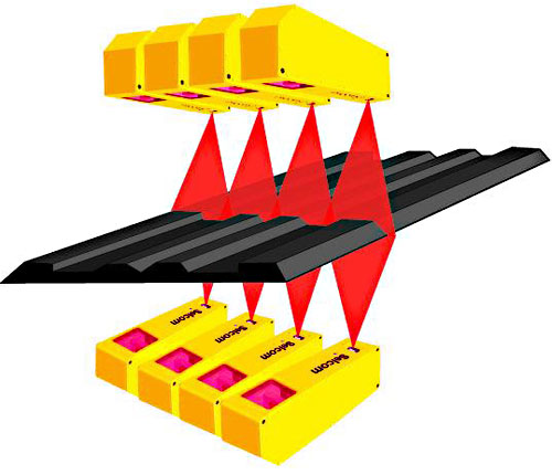
Four cameras above and four below the tread extrusion fully cover its surface. The system synchronizes the cameras and captures 3D images of both sides of the extrusion as it moves linearly under the scanning laser.
The platform also calibrates multiple sensor positions using an artifact of known dimensions, which is placed in the system measuring area. The process locates each sensor’s position with respect to a global coordinate system defined relative to the target. The system acquires parameters for each sensor during calibration, which transforms profile data from multiple sensors into a single coordinate system.
Smart communications
The large amount of collected data is analyzed with the inspection station’s remotely located host computer. The Gigabit Ethernet is widely used because it is easy to apply and implement. The network handles 1000 Mbps signals with inexpensive cables that easily run 100 m without repeaters. Power over Ethernet (PoE) shares the data transmission cables, which further makes the wired network simple and reliable.
Smart laser sensors are factory calibrated. They simplify the task of integrating the system and promote reliability by reducing the number of system components, which minimizes the number of possible failure points. Smart 3D sensor systems contain processors that solve the optical triangulation equations and apply linearization factors. They also automatically convert the measured values to engineering units and control the gain to ensure accurate measurements regardless of the variability in rubber surface texture and color. The internal processors also have capacity to handle specialized applications and software — such as measuring radial run-out and adjusting texture – which are supplied by the sensor manufacturer, the system integrator, or the end user.
Discuss this on the Engineering Exchange:
LMI Technologies
www.LMItechnologies.com
::Design World::
Filed Under: Automotive, SENSORS, TEST & MEASUREMENT

Tell Us What You Think!