by Mark Huebner, Market Development Manager, PBC Linear
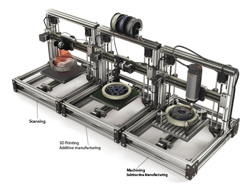
When evaluating the mechatronics for a scanning, printing, or machining device, 4 components and one characteristic are critical. Examining how each operates in a system and optimizing them will deliver equipment that produces the highest quality possible, whether for a hobbyist budget, or a large volume production of standard desktop units, or high-end stereolithography or medical scanning equipment.
Moving items between the digital environment and the real tangible world has become a common everyday practice in many areas of our lives. Scanning equipment passes people through security at the airport, digitizes images of patient or x-ray media for medical purposes, and reduces the input of data for creating a solid model to a single pass operation. Output equipment has advanced from flat printing on paper to digital printers with the ability to print onto a variety of media such as fabric, glass, metals, and more.
The Aluminatus 3D Printer from Trinity Labs utilizes Simplicity plain bearings, Simo Series linear stages, and Constant Force Technology lead screws from PBC Linear.
In recent years, 3D printing has brought rapid prototyping and the ability to create almost any shape to the desktop. Machines for more traditional subtractive production methods, such as routing, etching, or machining, can easily accept a scanned digital image directly and produce a physical item quickly.
When developing a new design for scanning, additive (3D printing), or subtractive equipment, considerations vary for the individual building his/her first 3D printer for fun, for a design team developing a reliable desktop model aimed at educational institutions, or for a group building high-end additive equipment for industrial use. In each case, however, there will be five basic design areas that affect the quality, repeatability, and life of a given system. When optimized for the application conditions, the complete mechatronic system will deliver quality results
The five areas to evaluate are:
1–Guide Rails
2–Bearings
3–Power Transmission
4–Electronics
5–Manufacturability
1. Guide Rails
Hardened steel round shafts or profile rails are ground to tight tolerances and offer a smooth running surface for bearings. However, when it comes to mounting them in parallel situations, they can be difficult to work with–requiring special fixtures, lasers, or other equipment for alignment. Any misalignment will result in inconsistent frictional forces, which will affect the desired smooth motion of a part, such as a camera or print head. In addition, mounting surfaces require precise manufacture as well, usually being ground or machined, which adds cost to the overall assembly.
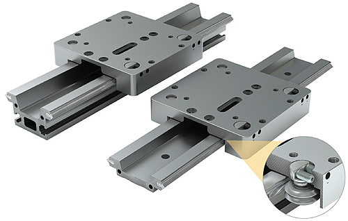
V-Guide wheel roller bearings with qualified
hardened steel raceways hold tight tolerances for bow, twist, and warp.
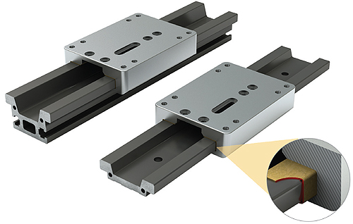
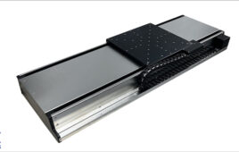
One-piece pre-aligned rails or guides are available in various forms and offer an alternative to traditional component assemblies. Variations include:
• an aluminum base with either round or V-style hardened steel embedded raceways
• a complete aluminum extrusion designed to operate with sliding bearings.
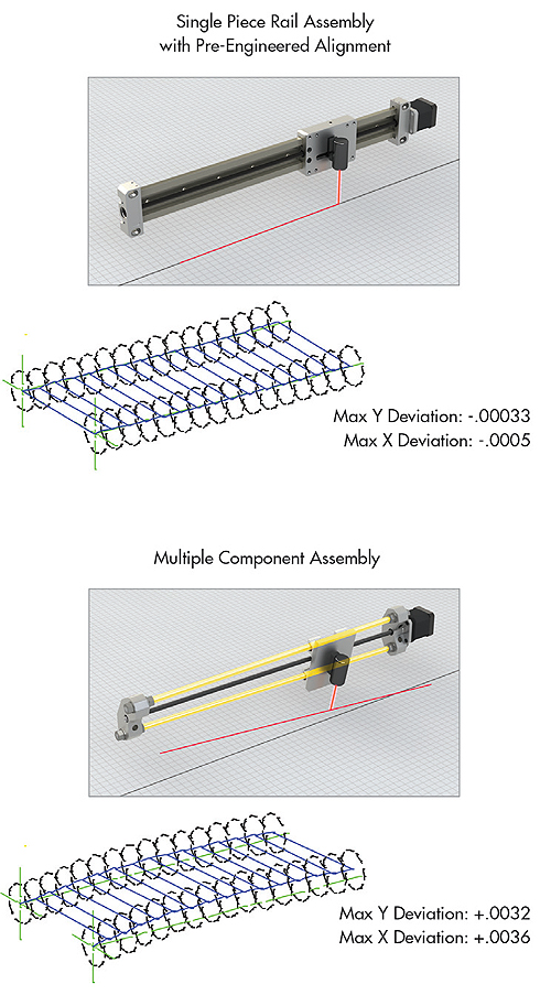
Shown here–a graphical model of actual inspection reports for flatness, straightness and parallelism comparing multiple components to a qualified one-piece linear guide rail.
Be aware when evaluating aluminum rails that some hold “as extruded” tolerances that will not achieve the precision needed for scanning, printing, or machining applications. Advances in manufacturing methods by some manufacturers will produce tight tolerances for bow, twist, and warp while maintaining the cost advantages of an aluminum extrusion. Additionally the pre-alignment of raceways cuts the cost of assembly and produces consistent results in input or output devices.
Individually mounted guide rails are difficult to align, adding cost and reducing performance.
2. Bearings
Plastic insert bearings (which are a common choice in low-cost scanning, printing, and subtractive machine designs) are usually low in cost, but tolerances may not be as tight as necessary for the application. The plastic is injection molded and so may not have undergone machining operations to the inside diameter. Often, tolerances are not sufficiently tight for the extruded aluminum rail the plastic bearings run over. The lack of tolerance control on both parts can impact frictional forces within a single piece of equipment and make repeatable assembly from machine-to-machine difficult.
Plain bearings with PTFE based Frelon® liner eliminates metal-to-metal contact and is self-lubricating.
Recirculating ball bearings, whether round or square bearing blocks, provide stiff preloaded low-friction motion, which can overcome some misalignment issues. With good loading and moment capacities, bearings deliver a rigid, precise movement over the rail because play is eliminated. However, true precision is ultimately a function of the entire system working together, including power transmission and electronics.
Problems can arise in quality output due to metal-to-metal contact. The small ball elements not only contact the steel shaft, they also bang against one another creating impact vibrations, which are picked up in the electronics. This action can result in irregular artifact lines on both digital images and in printed parts.
Roller bearings minimize the metal-to-metal contact to a single line for each bearing while maintaining preload adjustability. They also move smoothly for high-speed operation, such as that found in extremely fast printing applications. Roller bearings have load capacity advantages especially where moments or side loading are factors. They can be sealed against contamination and the large wheel diameter is good for rolling over or moving particulates.
Bronze bearings riding on a round hard steel shaft are another alternative. They have a high coefficient of friction that tends to remain consistent, but the metal-to-metal contact along with relaxed tolerances can reduce quality output.
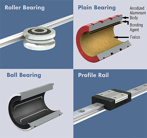
A bonded PTFE based bearings is an alternative that eliminates metal-to-metal contact and has the most consistent coefficient of friction performance, along with being precision ground to exact tolerances. The material is also adaptable for use on both round shafts or pre-aligned rails and guides. These features help to produce quality results in both input and output devices.
3. Power Transmission
Ball screws have distinct mechanical advantages when driving linear motion, and much like preloaded recirculating ball bearings, they deliver precise, low friction movement. Problems can arise, however, with the metal-to-metal contact with the small steel balls; the vibrations and feedback through the electronics have an impact on quality. Cost also tends to rise due to the amount of precision required in their manufacture. Lower efficiencies, though, typically do not come into play with the relatively light loads associated with a number of scanning, printing, or machining platforms.

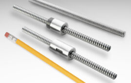
Lead screws with polymer nuts are a cost effective alternative for all three applications. Cost is less due to fewer moving components and easier manufacturing processes. Performance advantages, such as eliminating metal-to-metal contact and having consistent frictional forces, result in the highest quality output possible in scanning or printing. Larger leads, producing up to 25 mm movement per rotation, make them an alternative for high-speed applications where greater control than a belt can deliver is required.

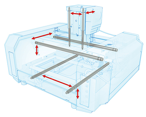
The alignment of all rotating elements is crucial to a linear system. “Wobbling” results in poor image quality. Shown here: red = motor alignment, green = coupling alignment, blue = screw alignment.
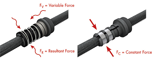
Two types of nuts with anti-backlash control have emerged for lead screws:
• Traditional anti-backlash nuts use a coil spring and collet design that transfers a variable force to eliminate play or backlash from the system. The advantage of this system is that it can usually be adjusted manually, but the resulting force can change rapidly and preload can be lost.
• Constant Force (CFT) type nuts apply a uniform consistent pressure to the nut at all stages of a motion profile and throughout its life. The drive mechanism can accelerate, brake, and corner fast compared to the “springy” effect and cogging of a reinforced belt and pulley design. This belt “plucking” can result in a moray pattern or loss of sharpness in features such as holes or cavities.
Belt driven systems provide high-speed operation at moderate cost. Typically having more components in an assembly, belt drives can be time consuming to install and adjust. They are harder to fine tune for shorter strokes due to the “cogging” effect of the belt on the pulley. Belts tend to perform best at longer lengths, beginning above 500 mm of stroke.
4. Electronics
Motor: Stepmotors are the lowest cost option for motion control and have simple wiring and few connections. Thus, they are an attractive option for basic or standard desktop type equipment. They produce high quality results when paired with anti-backlash lead screws that minimize the impact of the “jerks” felt from each step. When combined with belt drive systems, however, this effect can be magnified due to the “cogging” noted in the previous section.
Servo motor systems are costly, more complex to setup and program, and require more fine tuning, but the level of control and quality of image or product can be increased for high end machines.
Feedback: Open loop, or non-feedback controllers are low cost and easy to implement. But because no actual measurement of the position or product is registered, the highest quality input or output will be difficult to achieve.
Rotary encoders improve quality because a measurement of position does take place. This measurement, however, is of the motor position and assumes that the mechanical system of bearings, guide, and drive have no variance.
Linear encoders will provide the highest quality input or output based on the fact that a measurement of position is taking place at the point of interest for the machine. It gives real time feedback as to position of the scanning, printing, or machining head.
5. Manufacturability
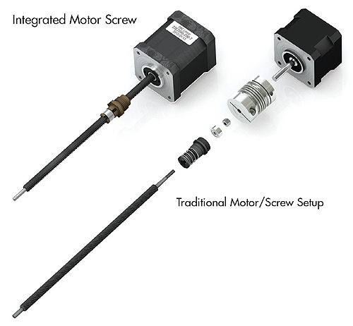
Ease of Assembly: A prime consideration for any system is the ability to make and assemble various components easily at low cost while maintaining consistent alignment. One example would be the connection of the motor to a lead screw. By integrating the screw with the motor and eliminating a coupler, not only will the assembly process be simpler and the number of parts and cost reduced, but the quality will improve as well. Tolerance stack up is eliminated, reducing concentricity and runout while improving rigidity. Kinematics is also enhanced due to a reduction in the rotating inertial mass.

Shown –compare images of 3D printers: (left) Typical component design with hundreds of parts; (right) Engineered assembly significantly reduces the number of components. Read more in the 3D printing application story in this issue.
Another example is in the evaluation of rails and bearings. Cost-to-performance requirements are often best met with 2-piece qualified and pre-aligned rails and integrated bearing carriages versus multi-piece components with difficult alignment and assembly of individual rails and mounting of individual bearings. This type of critical approach to analyzing components and assemblies can be applied in each area of a platform’s design review.
PBC Linear® helps Trinity Labs Build 3D printing Success
Trinity Labs is a Cartesian robotics R&D company located in Portland, Oregon that “envisions a world in which the conventional barriers between idea and reality are a thing of the past.” Their dedication to this goal goes far beyond words as they continually develop and advance 3D printing (3DP) technology–while making it accessible to both the hobbyist and serious engineer alike. With a range of components for the RepRap community, retrofit kits for those looking to upgrade, and complete professional desktop 3D printers, Trinity Labs makes it easy to engage in the 3DP realm without the high startup costs associated with many rapid prototyping options.
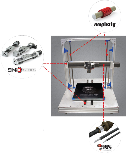
The Aluminatus 3D Printer from Trinity Labs utilizes Simplicity plain bearings, Simo Series linear stages, and Constant Force Technology lead screws from PBC Linear.
A key facet of the quality that Trinity Labs offers is the stable motion provided by PBC Linear for the “X” and “Y”-axis. The low profile UniGuide™ (UGA) is a simple 2-piece system. It is made up of a one-piece linear rail that has all of the critical surfaces machined with the patent pending one-pass SIMO® process developed by PBC Linear. This process virtually eliminates bow, twist, and warp for a precise, but cost effective linear guide. The carriage is also aluminum with integrated bearing pads permanently bonded directly to the carriage. These bearing pads are made of FrelonGOLD®, a PTFE based material that is self-lubricating, and that delivers consistent smooth motion. The clearance between rail and carriage is held to exacting tolerances, creating a tight fit to the rail that is reflected in the quality output. This ultimately leads to greater control of the buildup of materials on the 3D printer bed. Together, the UGA rail and carriage assembly are part of a retrofit kit for existing machines in the field and for the redesigned MendleMaxPro model from Trinity Labs.

The original design used a dual shaft linear system with bronze bushings. It required multiple components, fixtures, and a time-consuming assembly process to align the shafts so the bearings would move freely without binding. The 2-piece Uni-Guide design eliminated these assembly and alignment processes, saving time and making it an easy field retrofit for existing machines.
For the retrofit kits for existing printers, Ezra Zygmuntowicz, Founder and President of Trinity Labs said, “This is now the highest quality Y-axis solution in the open source RepRap 3D printer community ecosystem. The low profile UniGuide has given us a huge improvement in performance and customer satisfaction. It really caused a stir until we began shipping because people were so anxious to get the new version of the MendleMax. Our orders have just exploded. In addition, we have started using the UniGuide in a Y-axis upgrade kit for the Prusa Mendel RepRap printer. There is a large install base that will love to get their hands on this.”

Recently, Trinity Labs released a new desktop printer designed to make higher precision 3D printing more affordable. The Aluminatus TrinityOne platform uses the SIMO® Series lead screw driven rails on the “X” and “Y”-axis. These driven systems are based on the same UGA rail and carriage, but also integrate a Constant Force™ lead screw and nut to drive the carriage. The Aluminatus design further reduces the number of components for assembly. The reduced part count has gone from 400 pieces to 35 with overall assembly time dropping from 40 hours to under 2 hours.
The combined technologies of SIMO Series and Constant Force Technology (CFT) provide the Aluminatus with the high quality linear motion needed to meet Trinity Lab standards and increase the 3D printing objectives. Previously used belt drive systems held a repeatability of +/- 0.1 mm/m for linear position, with the smallest layer height at 100 microns. With SIMO Series and CFT, the Aluminatus has repeatability to +/- 0.02 mm/m and a layer height of 50 microns. These tolerances are possible because the CFT lead screw technology allows the drive mechanism to accelerate, brake, and corner fast with responsive precision as compared to the “springy” effect and cogging of a reinforced belt and pulley design. This belt “plucking” can result in moray patterns or loss of sharpness in features such as holes or cavities. An additional benefit of the greater control with CFT lead screws is that the Aluminatus can use the entire 300 x 300 x 350 mm workspace without worry of parts losing quality as the height increases.
Recognizing that part of Trinity Labs’ success with retrofit kits and new machines can be directly traced to the low profile UniGuide, SIMO Series linear guides, and Constant Force Technology lead screws, Ezra says that “we expect to be selling a lot of these X-Y-axis solutions and are looking for potential Z-axis applications for future printers we have on the horizon.”
PBC Linear
www.pbclinear.com
Filed Under: Digital manufacturing, Ballscrews • leadscrews, Encoders • linear, Encoders (rotary) + resolvers, LINEAR MOTION, MECHANICAL POWER TRANSMISSION, Mechatronics

Tell Us What You Think!