by Kyle Thompson, Associate Product Line Manager, Thomson Industries, Inc., Radford, VA
Configured linear motion assemblies can help reduce engineering and assembly costs as well as leadtime.
Designing linear motion assemblies can take up quite a bit of engineering time, not to mention the time and cost to assemble the components. At the same time, performance demands on machines, especially packaging machinery, are changing with customers asking for more sophisticated and versatile machines. For instance, take coil machines. In recent years, the market has demanded more sophisticated coil feeding equipment in order to maximize the number of parts produced from the coil strip.
One machine manufacturer, Minster Machine, has begun using pre-configured linear motion assemblies that are provided ready to bolt into its machines. The reason for this transition? “Switching to configured linear motion systems enables us to deliver lower cost custom coil handling equipment to our customers in less time,” says Rodney Lyons, Mechanical Engineering Manager for Minster Machine. “Some of our customers are very price sensitive so our ability to provide custom coil handling systems at a lower price has helped us to get stamping machine orders that we would not have gotten in the past.”
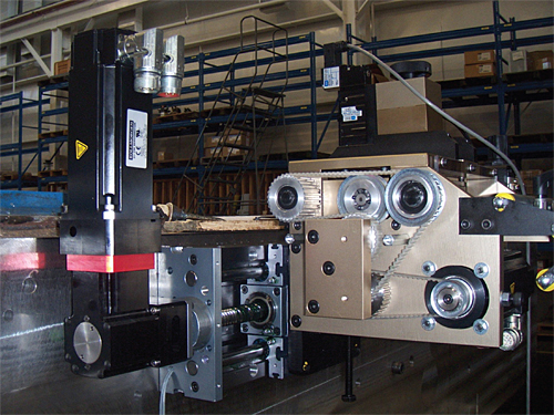
Minster Machine uses the Linear MOTIONEERING web-based sizing and selection tool from Thomson to help design the linear motion system for the company’s Zig Zag Roll Feeder. By doing so they have reduced the time required to design a custom linear motion system from about 3 hours to 30 minutes.
Minster engineers simply call in the specifications of custom linear motion systems to their integrator who in turn plugs the specifications into Linear MOTIONEERING® a web-based sizing and selection system from Thomson that configures a custom linear motion system optimized for the application. Thomson designs and assembles the systems, saving Minster substantial time and labor. Minster estimates that it’s reduced linear motion systems engineering time by 90%, material cost by 33%, and assembly time by 94%.
The Standard Approach
The shift to pre-configured assemblies is illustrated by Minster’s Dynamic Zig-Zag roll feeder, which feeds material in a simultaneous X-Y movement, allowing incoming material to travel at high speed through the rolls on the x-axis. The x-axis roll feed is driven by an AC servo motor while the y-axis movement of the feed is powered by a combination AC motor and linear ball screw. The linear ball screw maximizes speed and provides high torque and low inertia. Like the standard single axis Dynamic Roll Feed, the Zig-Zag is compact and can easily be mounted to any side of a press.
“The challenge of providing Zig-Zag roll feeders is that every customer wants something a little different,” Lyons said. “We have built feeders with y-axis travel ranging from 6 to 18 in. The motion profile and the size and weight of the coil also affect the design of the feeders. Customers are asking that stamping machines and feeders be delivered in much less time than in the past. In the past we might have 8 to 10 weeks to design, build and ship a machine while today a more typical leadtime is 2 weeks. This means that the time available to design and release the machine to manufacturing is reduced from two weeks to two days. At the same time, customers are more price sensitive than they have ever been in the past and we have to compete with other machine suppliers from around the world.”
In the past, Minster designed and built the slides used to provide y-axis motion for the Zig-Zag roll feeders. When the company received an order, Lyons assigned an engineer to design the linear motion system. The engineer began by gathering up the requirements of the application such as the length of travel, system orientation, load, required life, environmental conditions, positional requirements, and required speed and acceleration. The engineer used handbook calculations to design the linear motion system and produce a solid model and manufacturing drawings of the design.
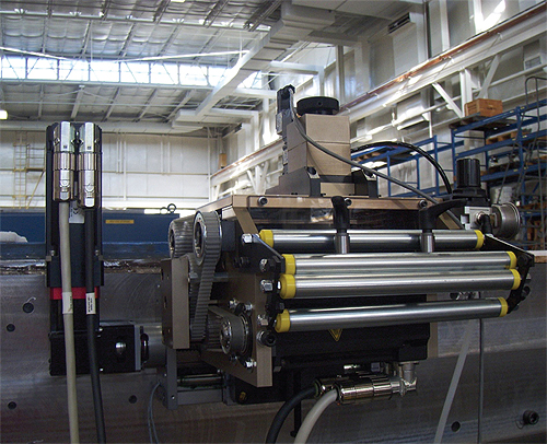
The Dynamic Zig Zag Roll Feeder from Minster Machine with Thomson SuperSlide 2RB continuously supported systems with linear rails, integral ball screw assemblies and T-slot cartridges.
The engineer typically sourced the components such as the servo motor, ball screw, linear or profile rails, 90 degree reducer and coupling from several different suppliers. It took about 20 hours of engineering time to design the linear motion system and the cost of the components averaged about $6,000. When the components were received, it took about four hours to build the slide and then another 30 minutes to install it in the roll feeder.
The configured assemblies approach
Lyons decided to take a look at a new approach using configured assemblies that provide the exact features, performance and form factor required for an application and that are less than the cost of the individual components.
Lyons works with a local linear motion integrator, i-Automation, to configure custom assemblies that are matched specifically to the requirements of their application based on economical and readily available standard components. When a new order is received, Lyons now calls Ryan Glenn at i-Automation and provides the specifications for the linear motion system. Glenn uses Thomson’s web-based sizing and selection system to design a customer linear motion system. Glenn enters the key parameters of the application including mounting configuration, positioning requirements, environmental conditions, loading conditions and move requirements. With the web-based program he can also sort potential solutions by lead time, with many available for shipment in just one week.
i-Automation provides Minster with a quote and a CAD file of the proposed design within 24 hours of the request. The cost of the typical system is about $4,000 and additional time is saved in the purchasing process because only one supplier is involved. This approach also reduces Minster’s engineering time to only two hours so Minster can focus its engineering resources on its core competencies while taking advantage of the linear systems supplier’s extensive experience.
When the linear motion system is received, Minster personnel merely set the limit switches, bolt the adapter plate of the carriage to the feeder and bolt on the servomotor. It takes only 15 minutes to complete the assembly of the linear motion system, and the time to assemble the linear motion system to the feeder is just 30 minutes.
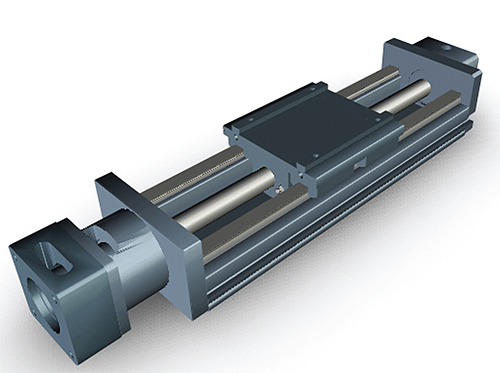
This is a model of Thomson’s AccuSlide 2HB generated by Linear MOTIONEERING. The 2HB is a continuously supported profile rail system with carriage and integral ball screw assembly that Minster Machine uses for continuously supported applications that require high stiffness and rigidity.
“Our move to configured assemblies saves a considerable amount of time and money.” Lyons said. “The key attributes of the new approach include the avoidance of canned solutions, a robust product development process, use of modified or configured parts where practical, selection of suppliers capable of delivering complete systems rather than simply parts, and the use of online selection and configuration tools. We have virtually eliminated the need for our engineers to spend time on designing linear motion systems, which gives us more time to focus on what we do best. We are also saving considerable time in the assembly process. The delivered cost of the complete linear motion system is lower than the total cost of the components that we previously purchased to build our own linear motion system. The improvement in product performance and reduction in time to market and engineering costs is helping us to increase market share.”
Profile rail versus linear rail solutions
When choosing between different rail technologies for linear motion applications, the choice will depend on the application demands. Profile or square rail systems offer high accuracy, high rigidity and high load-life capacity, in addition to being compact. Their key advantage is derived from ball conforming grooves on both inner and outer races that increase load capacity relative to standard round rail guide. For the particular sizes used by Minster, the profile rail solution provides more than twice the load capacity of a round rail system. The ball track groove in profile rail guides is only slightly larger in radii than that of the balls themselves. The geometry cradles the balls as they infinitesimally flatten under load, slightly expanding the contact area between the balls and the races. As a result, profile-rail bearings are roughly 10 times stiffer than a traditional round rail assembly with convex ball and shaft surfaces. Profile rail guides can provide positioning accuracy from 0.0002 to 0.001 in. over 10 ft. They can be preloaded from 3 to 13% of rated dynamic load to further reduce deflection.
For applications requiring moderate stiffness and rigidity, a linear rail system has some advantages. A key advantage of linear rail systems is their ability to accommodate torsional misalignment caused by inaccuracies in carriage or base machining or machine deflection with little increase in stress to the bearing components. The self-aligning-in-all-directions design of round rail bearings is forgiving of poor parallelism and variations in rail height. As a result, these bearings allow smooth travel when mounted to wider-tolerance prepared surfaces. In end-supported applications, the axis of motion of round rail guides is established entirely by fixing the two ends of the shaft. It doesn’t matter what the surface of the machine is like between these two points or whether there is one at all. So linear rail systems are capable of spanning gaps up to 24 times the shaft diameter. The accuracy of the guide depends only on the accuracy of the end-support mounting.
How the Ideal Linear System is Selected – in Minutes instead of Hours
Minster Machine works with a local linear motion integrator, i-Automation, to configure custom assemblies using Linear MOTIONEERING. The assemblies are matched specifically to the requirements of the application based on economical and readily available standard components.
Required inputs include:
- Selecting the system orientation
- Entering the positioning requirements
- Specifying environmental factors
- Configuring load and force
- Defining move profile requirements
With that information, Linear MOTIONEERING provides i-Automation with:
- A filtered and sortable list of solutions that fit the application requirements
- Downloadable 3D models, with pricing and ordering information
- The ability to save the configuration for future reference and use on subsequent projects
Thomson Industries, Inc.
www.thomsonlinear.com
Minster Machine Company
www.minster.com
i-Automation
www.i-automation.com
Filed Under: LINEAR MOTION, Motion control • motor controls

Tell Us What You Think!