By Dan Jones, President, Incremotion, Thousand Oaks, Calif.
One of the oldest motor technologies, brushed dc motors have been around since the beginning of the age of electricity. These low cost options with high peak torques driven by the simplest of variable speed controllers suit a variety of application needs.

The brush dc motor has been around for the better part of 150 years. It comes in a variety of configurations, but the two types, the wound field and the permanent magnet, remain the most common today. In 2009 it accounted for over 275 million motors used in US applications. Automotive and appliance applications lead the way today. And although newer motor technologies such as the brushless permanent magnetic synchronous motor (PMSM) and the switched reluctance (SR) motor have replaced the venerable brush dc motor in many office, medical, factory and defense applications, brushed dc motors are still a viable motor technology.
The Wound Field DC Motor
There are 2 main types of brushed dc motors; the wound field and the permanent magnet dc motor.
The wound field dc motor uses a wound field coil in series with the rotating armature and can be driven by dc or ac input voltage. It carries a very descriptive name; the universal motor. With either input power these motors can operate at speeds above 10,000 rpm in vacuum cleaners. They can also be used in battery operated power tools.
The permanent magnet (PM) dc motor is a more recent development (the 1950s) and has replaced the universal motor in many power tool applications. Automobile auxiliary applications including window lift, windshield wipers and car seat adjust are examples of the PM brush dc motor in use in large quantities today. The PM motor possesses a linear set of torque, speed and current performance curves under a wide range of application loads.
The Commutation System
The heart of a brushed dc motor is the commutation process.
The mechanical switching system, called the commutation system, is needed to switch current polarity through the armature windings to allow the armature to continue smooth rotation. This mechanical contact system separates the brush dc motor from all other types. The dc motor’s commutation system is composed of 4 major elements:
1. Commutator (mechanical switching assembly)
2. Brush assembly (brush, shunt and spring)
3. Brush holder (brush position system and interconnection)
4. Commutator film
The cartridge type brush holder assembly is representative of a number of brush and brush holder assembly types.
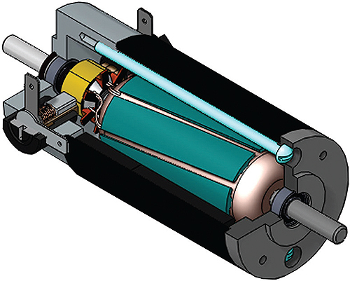
A cutaway view of a typical brushed dc motor, like the one pictured here from Dynetic Systems, shows the rotor and stator as well as the commutator(in yellow) and the brush assembly.
The film on the commutator surface is by far the most tenuous member of the commutation system. It functions as the interface between the copper commutator and the metal, carbon, graphite or combination brush. This film is composed of copper and brush debris, copper oxides, moisture and other compounds available in the surrounding air. The typical film on the commutator has many necessary functions. It acts as a partial barrier between the metallic surface of the commutator and the brush itself. The motor’s drawn current punches multiple pin holes through the film that are broken when the commutator rotates. The act of making contact and breaking contact constitutes the sliding process of transferring power from the brush assembly to the rotating commutator. The commutator film thickness, consistency, and color are indications of the proper or improper function of this all-important super-thin film. There is no mathematical model that can be used to predict successful commutator and brush wear operation. History and experience are the guide for a viable solution.

The graph shows typical torque-speed curves for common varieties of brushed dc motors.
The Brush
The brush material is critical to the successful life of the dc motor. It must possess the following attributes:
• Follow the unevenness of the commutator
• Absorb, without damage to either brush or commutator, the current pulses that occur during the process of current reversal
• Return to a stable operation, when external circumstances, such as high current overloads, widely different operating conditions and unusual environmental conditions occur
• Possess the proper electrical and mechanical size and location with respect to the commutating neutral zone
• Maintain the desired brush pressure using a properly selected spring against the commutator surface
The selection process for brush materials is highly application specific, depending on the desired life and operating conditions of the application.
Carbon in its many forms constitutes the bulk of all dc motor brushes. Graphite, a form of carbon, is used in most applications because it is in itself a dry lubricant. Additives to graphite such as copper and silver help the brush carry higher electrical currents. These brushes are designated metal graphite. Other brush compositions include electro-graphites, resin bonded graphites, carbon graphites and carbon. The electro-graphite brush is a special crystalline form of graphite that is created by baking the brush at a high temperature. They are softer and possess no impurities and work well in high voltage (above 100 V) applications. Each brush material has its application based “sweet spots” (see table below).
Brush Wear
The brush is designed to wear, but not too quickly. Brush wear can be traced to conditions that cause mechanical wear and electrical wear.
Mechanical wear is a function of total distance travelled at a specific base speed in feet per second. Brush pressure should vary between 3 PSI to 10 PSI, depending on the brush grade. As the brush wears, the brush pressure will decline over time, so its a good idea to set the beginning pressure at the high end of the acceptable pressure range. Fortunately, the wear rate pattern is acceptable over a wide range of PSI values. Each dc motor commutation system has a maximum speed. In most cases mechanical wear rates are near linear. A round concentric commutator (within 0.001 TIR or Total Indicator Readout) will eliminate conditions that accelerate brush wear exponentially due to the large electrical arcing that can occur.
Electrical wear is a non-linear condition that causes premature brush failures. Severe arcs and sparking occurs that disrupts the commutator film and burns the commutator surface. Too low a brush pressure, too high a current density (for the chosen brush material), too fast a motor speed (for the chosen brush material) too dry and too hot an operating environment will lead to arcing and sparking and excessive brush wear. The wear rate could increase by a factor of 4 or 5 times.
The Brush Grade Selection Process
How do you select the best brush grade for the longest brush life? You cannot model it and so must use your own knowledge and experience, so you have to review previous successful brush selections in terms of earlier application solutions. Most experienced motor designs have a cadre of successful brush grades. The brush supplier applications engineer can also assist you in the selection process. The brush suppliers continue to refine the various brush grades, control the manufacturing process more effectively, and collect the brush’s operating conditions more completely.
Why Use a Brush DC Motor?
If the brush selection process is so complicated and subjective, why not switch to a different type of motor? The brush dc motor is a lower cost option with a linear torque/speed performance. It develops higher peak torques and is driven by the simplest of variable speed controllers. While it may not be for the faint of heart, it does the job for a wide range of higher volume applications.

Discuss this on The Engineering Exchange:
::Design World::
Filed Under: Automotive, Motion control • motor controls, Motors • dc

Tell Us What You Think!