Active magnetic bearings (AMBs) present unique advantages over conventional roller or fluid-film bearings when designing high-speed rotating machinery, such as turbines, compressors, Organic Rankine Cycle systems and flywheel energy storage systems. Unlike conventional bearings, AMBs suspend the target rotor in a magnetic field. The result is a non-contact rotor support system with extremely low friction and no contact wear.
What follows is a simplified explanation of how active magnetic bearings work and how they can benefit high-speed rotating equipment.
How AMBs Work
Magnetic bearings are devices used to levitate objects using magnetic forces. Some magnetic bearings provide a full non-contact support of an object, whereas others provide only a partial support working together with more conventional mechanical bearings.
While a wide variety of magnetic bearings have been developed, only one type has been widely accepted in the industry so far – active magnetic bearings. This is because AMBs can exert higher-density forces on surfaces of supported objects than any other type of magnetic bearings. They can also operate in a wider range of environments, and their properties can be made highly configurable through software parameters. Ongoing dramatic improvements in digital signal processors (DSP) enable faster performance, integration of important peripheral features and cost reductions, which further boost their commercial attractiveness.
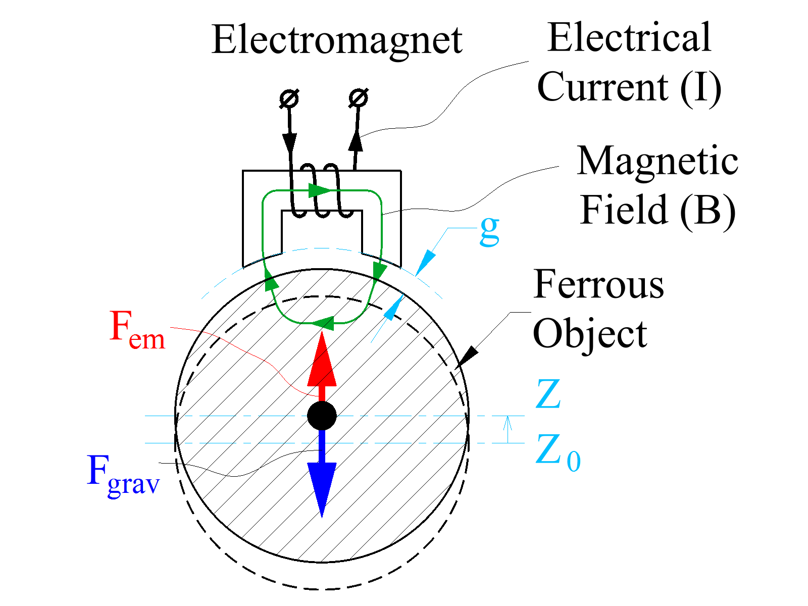
The basic operating principle of AMBs is very simple. A ferrous object is known to be attracted to a permanent magnet or an electromagnet (an electrical coil wound around a ferrous core). For example, Figure 1 shows a ferrous object, which will be attracted to an electromagnet located next to it whenever the latter is energized with a current. Note that the force between the electromagnet and the ferrous object is always attractive – it cannot be repulsive.

Figure 1. According to the basic operating principle of an active magnetic bearing, a ferrous object will be attracted to an electromagnet located next to it whenever the latter is energized with a current.
The pulling force exerted by the electromagnet on the object depends on two parameters: the current in the electromagnet and the distance between the object and the electromagnet. In order to achieve stable levitation, AMBs use non-contact position sensors to monitor shaft position and feed this information back into a control system. The magnetic bearing controller (MBC) uses this feedback to adjust the required current to a magnetic actuator to maintain proper rotor position.
Figure 2 shows a simple depiction of a complete radial bearing that can be used to support the shaft of a rotating machine. There are two control axes (X & Y) with each axis having a pair of electromagnets pulling the rotor in opposite directions. All industrial AMBs employ a bias flux to linearize the force current relationship of the actuator. The bias is generated in the bearing of Figure 2 by passing a steady bias current through the all of the coils. The MBC adds a control current to adjust the net current up or down from the bias level as needed to maintain desired position.
.png)
Figure 2. In this depiction of a complete radial bearing, there are two control axes (X & Y), each having a pair of electromagnets pulling the rotor in opposite directions.
Advantages of AMBs
There is no physical contact between rotating and stationary components in an AMB system, so friction and wear are minimized. Since there is no need for lubrication, AMB systems are virtually maintenance free, reducing initial capital investment as well as operating and maintenance costs. Their low power losses allow machines to achieve higher running speeds, higher efficiencies and longer machine life than conventional bearings. AMBs can also be used in harsh environmental conditions, including extremely low temperatures, zero gravity and corrosive environments.
A Graphical User Interface (GUI) is typically supplied with commercial AMBs to provide access to many features built-in to the control firmware, such as calibration, health monitoring, data logging and troubleshooting. Dynamic properties, such as stiffness and damping, can be easily measured and readily changed via interaction between the GUI and AMB firmware. In contrast, with conventional bearings, changing the dynamic properties would typically require a complete redesign, remanufacture, retest and reinstallation.
In addition, the high static stiffness of AMBs provide more precise control over the nominal shaft center under load, and AMBs allow for synchronous force rejection schemes (synchronous cancellation), which virtually eliminate transmission of rotor unbalance forces to the outside structure.
There are other advantages to using AMBs. Power consumption of advanced AMBs is typically negligible compared to the power rating of the machine they are used in. For example, a homopolar permanent-magnet-biased magnetic bearing system used in a 175 kW turbocompressor require less than 200 W of power for its operation. A heteropolar electromagnet-biased magnetic bearing for the same machine would consume more power but still less than 500 W.
Challenges and Solutions
There are some inherent losses within AMBs. The radial magnetic force exerted on a rotor by an AMB becomes weaker when the rotor spins at a sufficiently high speed. This is because the rotor, typically made of conductive soft-magnetic material, produces induced eddy currents when spinning in the non-uniform magnetic field needed to induce a radial force.
In order to reduce the eddy currents in the rotor, and, subsequently the loss of some radial force capacity, a portion of the rotor is normally made of electrically insulated steel laminations. Thinner laminations have reduced eddy currents and thus smaller force loss at a given rotational speed. The loss of radial force also depends on the frequency of the magnetic field that a rotor sees when spinning, or for a given spin speed, on a spatial frequency of the field distribution around the rotor. For example, a magnetic bearing with a magnetic field distribution having four cyclic changes around the rotor (Figure 2) will have lower load capacity at a given speed than a similar magnetic bearing with a magnetic field distribution having only one cyclic change.
The optimum solution to these losses is to use homopolar technology in which the field distribution has only one cyclic change around the rotor and only when the rotor is subjected to radial loading, unlike heteropolar designs in which magnetic field distribution around the rotor has at least four cyclic changes. A homopolar actuator is shown in Figure 3. The bias flux in this actuator is generated by axially polarized permanent magnets arranged around the circumference of the electromagnet. The bias flux flows into the shaft through a dead (solid, uncontrolled) pole and returns through a laminated path into the electromagnet. In this topology, the bias flux does is distributed in a nominally uniform manner around the rotor.
Another advantage of the reduced eddy current losses of the homopolar magnetic bearing technology is significantly lower heat generation in a spinning rotor. In fact, homopolar magnetic bearings will have almost no heat generated in the rotor at speed in an absence of a radial loading because the magnetic field will be almost uniformly distributed around the rotor, thus having no significant eddy currents generated. In contrast, heteropolar magnetic bearings generate heat in a spinning rotor even in the absence of radial loading. Low heat generation in both stationary and rotating parts of homopolar permanent magnet biased magnetic bearings make them very energy efficient and well suited for applications where heat extraction mechanisms are limited, such as in a vacuum.
Another critical component in an AMB system is the position sensors, which provide the magnetic bearing controller with accurate information about the rotor position unaffected by external factors such as speed, temperature, dust, working fluids and external magnetic and electric fields. While conventional magnetic reluctance sensors may work very well for measuring radial displacements, measurement of the axial displacements is often much more challenging. The recommended solution to overcome this challenge is to employ a constant-flux edge sensor. This provides clear performance advantages, including immunity to external magnetic fields and radial displacements, better temperature stability, broader measurement range, a pass-through rotor assembly and high raw gain in order of 100 V/in.
Limits and Contradictions
As far as operating speed limitations go, a magnetic bearing’s maximum RPM is only limited by the centrifugal stress that its rotor laminations can tolerate. In most magnetic bearing machines, the maximum speed is limited by stress on other rotor components such as the motor, impellers, flywheel hubs, etc., rather than the magnetic bearings.
Operating temperatures of the practical magnetic bearings are normally limited to 200 deg. C, primarily because commercial magnet wires are rated for this temperature. Higher operating temperatures are possible if more exotic wire types are used.
Some applications, including those with high dynamic loads such as reciprocating engines are poor choices for magnetic bearings because they have lower dynamic stiffness and load density than conventional rolling element and fluid film bearings. For similar reasons, magnetic bearings are usually not well suited for highly maneuverable vehicles like passenger cars. Gimbal mounted energy storage flywheels supported by magnetic bearings have been studied for use on rail cars and were found to be a viable technology.
System Integration – Putting AMBs to Work
AMBs are not off-the-shelf products. It’s strongly recommended to work with an AMB supplier that has the in-house multidisciplinary expertise to design the entire machine running on magnetic bearings. This achieves optimal performance of the machine as an integrated system and fully realizes the active magnetic bearing system potential.
Sidebar: Active Magnetic Bearings Survive Severe U.S. Navy Shock and Vibration Tests
The U.S. Navy recently successfully completed final production prototype shock and vibration testing for a new-generation High-Efficiency Super Capacity (HESC) Chiller System. Calnetix Technologies was responsible for the high-speed permanent magnet motor, magnetic bearings, magnetic-bearing controller and backup bearing systems for the two-stage, variable-speed compressor at the heart of the chiller system. The HESC VSD was developed jointly by Calnetix and Fairlead Integrated Power and Controls, with Calnetix providing the variable speed power module and controls.
With the successful shock and vibration tests, the HESC Chiller/VSD are now moving into the production phase, with the first shipboard installation taking place on the USS John P. Murtha (LPD-26). Other ship installations will continue production well into the next decade.
For MIL-S-901D Grade A heavy weight shock testing, the HESC Chiller was installed in a floating platform and subjected to a series of four shock impacts from high-explosive charges positioned 24-feet under the water with one blast 40-feet from the front of the floating platform and the other three blasts 30-feet, 25-feet and 20-feet from the side of the platform. The chiller was operating during three blasts and in standby mode for one blast. The backup bearing system of the compressor absorbed the shock impacts; the magnetic bearings recovered levitation as designed; and the motor performed without any issue. For MIL-STD-167-1A vibration testing, the chiller was mounted on a shaker platform and driven at varying frequencies and amplitudes in three axes while operating.
The HESC Chillers are expected to reduce ship acquisition and life cycle costs by increasing cooling capacity by at least 50 percent, improving reliability by more than 50 percent, and reducing chiller fuel consumption by more than 25 percent, all while meeting the environmental objectives of reducing refrigerant leakage by 90 percent and eliminating hazardous oily waste.
.png)
Figure 3. In this actuator, the bias flux in this actuator is generated by axially polarized permanent magnets arranged around the circumference of the electromagnet. The bias flux flows into the shaft through a dead pole and returns through a laminated path into the electromagnet.
Filed Under: Bearings, Industrial automation


