Design World

  • Home
  • Technologies
    • 3D CAD
    • Electronics • electrical
    • Fastening & Joining
    • Factory automation
    • Linear Motion
    • Motion Control
    • Test & Measurement
    • Sensors
    • Fluid power
  • Learn
    • Ebooks / Tech Tips
    • Engineering Week
    • Future of Design Engineering
    • MC² Motion Control Classrooms
    • Podcasts
    • Videos
    • Webinars
  • LEAP AWARDS
  • Leadership
    • 2022 Voting
    • 2021 Winners
  • Design Guide Library
  • Resources
    • 3D Cad Models
      • PARTsolutions
      • TraceParts
    • Digital Issues
      • Design World
      • EE World
    • Women in Engineering
  • Supplier Listings

Agilent Technologies Enhances the PCI Express® 3.0 Receiver

By Stacy Combest | February 1, 2013

Share

Agilent Technologies Inc. announced an enhanced solution for PCI Express® 3.0 receiver characterization, at DesignCon.

The Agilent PCIe® 3.0 receiver characterization solution provides complete and accurate receiver tolerance test results while minimizing R&D effort. The new J-BERT software (revision 7.40) enables testing of PCIe 3.0 receiver designs that adjust the length of the 128b/130b encoded filler symbols—also known as SKP ordered sets—as needed for clock compensation.

Using the Agilent test set, design and test engineers in the semiconductor and computer industry can accurately characterize and verify standard compliance of PCIe receiver ports in ASICs, add-in cards and motherboards.

Since the release of revision 3.0 of the PCI Express specification, the 8-GT/s interface has been designed into many computer platforms. A common reference clock often is used for PCIe designs, but more and more designs now require separate reference clock architecture with independent spread spectrum clocking (SSC) such as a PCIe-over-cable link. When designers use separate reference clocks, they need to compensate for small differences in the clock rate on the transmitter and receiver sides to avoid buffer overflow. Clock compensation can be required even for common reference clock designs on motherboards, in the presence of SSC or when using multiplying phase-locked loops. The PCI Express standard requires this compensation to be accomplished by adding SKP symbols to (or removing them from) the nominal SKP ordered set.

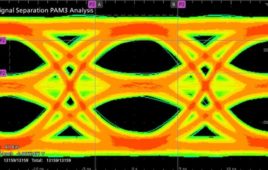
PCI Express 3.0 Receiver Test Setup with J-BERT N4903B

Agilent’s J-BERT N4903B high-performance serial bit-error ratio tester software enables receiver testing in cases where the SKP ordered set length is changed by the device under test in loopback mode. The J-BERT error detector can now ignore SKP ordered sets when counting errors, even when they deviate from the original length sent out by the pattern generator. When engineers debug their designs, they can monitor SKP ordered set counters in the error detector.

The Agilent receiver test solution encompasses the J-BERT N4903B high-performance serial BERT, the N4916B de-emphasis signal converter, the N4915A-014 PCIe 3.0-compliant calibration channels, the 81150A or 81160A pulse function arbitrary noise generator, an Infiniium 90000 or 90000 X-Series high-performance oscilloscope, and N5990A-101 and N5990A-301 test automation and link training software. For motherboard testing, the N4880A reference clock multiplier is available.

Agilent Technologies
www.agilent.com

Test & Measurement Tips


Filed Under: Test & Measurement Tips


Related Articles Read More >

eBay
When to buy used test equipment
TRACO Power now sells cost-optimized 1-A POL converters with 6-to-36-V input range
eye diagram
Simpler debugging for Automotive Ethernet systems
E+H-Prosonic-flowmeter
Flowmeter for industrial water, feedwater, cooling water and condensate

DESIGN GUIDE LIBRARY

“motion

Enews Sign Up

Motion Control Classroom

Design World Digital Edition

cover

Browse the most current issue of Design World and back issues in an easy to use high quality format. Clip, share and download with the leading design engineering magazine today.

EDABoard the Forum for Electronics

Top global problem solving EE forum covering Microcontrollers, DSP, Networking, Analog and Digital Design, RF, Power Electronics, PCB Routing and much more

EDABoard: Forum for electronics

Sponsored Content

  • Global supply needs drive increased manufacturing footprint development
  • How to Increase Rotational Capacity for a Retaining Ring
  • Cordis high resolution electronic proportional pressure controls
  • WAGO’s custom designed interface wiring system making industrial applications easier
  • 10 Reasons to Specify Valve Manifolds
  • Case study: How a 3D-printed tool saved thousands of hours and dollars

Design World Podcasts

May 17, 2022
Another view on additive and the aerospace industry
See More >
Engineering Exchange

The Engineering Exchange is a global educational networking community for engineers.

Connect, share, and learn today »

Design World
  • Advertising
  • About us
  • Contact
  • Manage your Design World Subscription
  • Subscribe
  • Design World Digital Network
  • Engineering White Papers
  • LEAP AWARDS

Copyright © 2022 WTWH Media LLC. All Rights Reserved. The material on this site may not be reproduced, distributed, transmitted, cached or otherwise used, except with the prior written permission of WTWH Media
Privacy Policy | Advertising | About Us

Search Design World

  • Home
  • Technologies
    • 3D CAD
    • Electronics • electrical
    • Fastening & Joining
    • Factory automation
    • Linear Motion
    • Motion Control
    • Test & Measurement
    • Sensors
    • Fluid power
  • Learn
    • Ebooks / Tech Tips
    • Engineering Week
    • Future of Design Engineering
    • MC² Motion Control Classrooms
    • Podcasts
    • Videos
    • Webinars
  • LEAP AWARDS
  • Leadership
    • 2022 Voting
    • 2021 Winners
  • Design Guide Library
  • Resources
    • 3D Cad Models
      • PARTsolutions
      • TraceParts
    • Digital Issues
      • Design World
      • EE World
    • Women in Engineering
  • Supplier Listings