Air gaging relies on a law of physics that states flow and pressure are directly proportionate to clearance and react inversely to each other. As clearance increases, airflow also increases and air pressure decreases proportionately. As clearance decreases, airflow also decreases and air pressure increases.

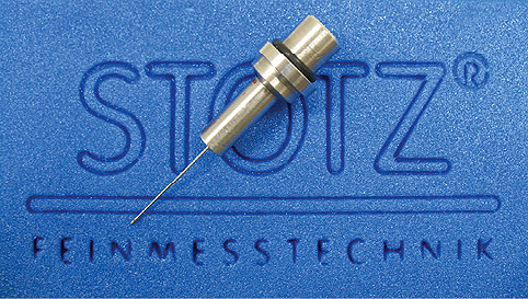
“The size of probes continues to get smaller and smaller and can now be as small as 0.6 mm (0.024 in.) in diameter.”
This is accomplished by having a regulated airflow that travels through some type of restriction such as a needle valve or jeweled orifice and then through the nozzle in the air tool. As the obstruction (work piece) is brought closer to the nozzle, airflow is reduced and the back pressure is increased. When the nozzle is completely obstructed, the flow is zero and the back pressure is equal to the regulated air. Conversely, when the nozzle is open to the atmosphere, airflow is at a maximum and the back pressure is at a minimum.
There are several varieties of air gaging systems that include back pressure bleed, differential and flow type systems.
The back pressure bleed system is the most versatile. Tooling from different air gaging systems may be used with this type. It is configured with an air pressure regulator to control the incoming air pressure to ensure maximum linearity. It is the second restriction that allows the user to adjust for different air gage tooling by adjusting the incoming air pressure to match the style of air tooling used. This type uses two setting masters to calibrate. The masters are typically at the MIN and MAX of the tolerance of the work piece. This allows for linearity of the measurement through the entire measuring range. Because it is a two master system, each time you calibrate, you are compensating for any wear, dirt build-up or minor damage to the tooling.

“The air tooling has no moving parts and therefore has a very long and dependable service life.”
The differential system divides the air stream into two fixed restrictions. One side ends in a zero valve, which balances pressure to the fixed second leg of the system, which ends at the air ring or plug. A differential pressure meter that bridges the two legs measures the difference between these legs. This type uses a single master to set it to zero. Tooling for this type of system needs to be ordered for each particular magnification. This system is not as forgiving with worn or damaged tooling because you are using a single calibration point. Any part not made near the zero is more likely to have an inaccurate reading. This becomes more of an issue as you reach the outer limits of the tolerances.
The flow system is measured and read in a flowmeter tube that supports a float. This system uses two masters for calibration. It is similar to the back-pressure bleed system in its accuracy across the tolerance range. The range of magnification is adjusted by changing flow tubes and scales and is not as simple as the back-pressure bleed system. The flow system requires a much higher volume of air, which requires much larger nozzles. Because the nozzles are larger, the nozzle must be kept closer to the part and therefore has a smaller nozzle drop. This can shorten tool life. The flow system can be used with long hoses without affecting the response time of the amplifier, which makes it a candidate for long holes such as gun barrels.
Air gaging is designed to be used on work pieces with tolerances of 0.005 in. or smaller. The resolution and repeatability of the measurement can be in the millionths of an inch. Because air gaging is a non-contact method, it is useful for measuring soft, highly polished, thin walled and other materials susceptible to marking. This is a problem when using a contact gage such as a micrometer or dial bore gage.
Air gaging can be used to measure complex geometric tolerances such as diameter, taper, parallelism, squareness, flatness and matching of components. These may not be able to be checked with fixed limit gaging or may be costly and time consuming to check in a different way.
These systems operate at air pressures that can remove contaminants such as abrasive particles and coolant, which will eliminate the need for a separate cleaning in most applications.
Air gaging technology is continually improving as computer technology continues to evolve. These systems can range from simple desktop readouts to full SPC computers with contour scanning capabilities. As manufacturing requirements continue to become more complex, air-gaging technology evolves to meet the demand.
Advanced Machine & Engineering Co.
www.ame.com
Filed Under: Aerospace + defense, MORE INDUSTRIES


Tell Us What You Think!