Design World

  • Home
  • Technologies
    • 3D CAD
    • Electronics • electrical
    • Fastening & Joining
    • Factory automation
    • Linear Motion
    • Motion Control
    • Test & Measurement
    • Sensors
    • Fluid power
  • Learn
    • Ebooks / Tech Tips
    • Engineering Week
    • Future of Design Engineering
    • MC² Motion Control Classrooms
    • Podcasts
    • Videos
    • Webinars
  • LEAP AWARDS
  • Leadership
    • 2022 Voting
    • 2021 Winners
  • Design Guide Library
  • Resources
    • 3D Cad Models
      • PARTsolutions
      • TraceParts
    • Digital Issues
      • Design World
      • EE World
    • Women in Engineering
  • Supplier Listings

All about multi-flex cable carriers used on robotic arms

By Mary Gannon | July 16, 2021

Share

Black plastic conduit pipe for multiflex cable carriers

Contributed by Jody Muelaner

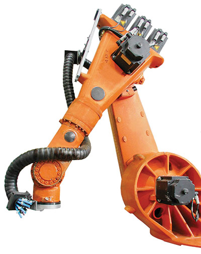
Good cable management is vital to the accurate and reliable operation of an industrial robot. Cables that catch and snag will affect the accuracy of a robot. Over time they will result in unplanned maintenance and excessive downtime. Robotic cell integrators have identified cable issues as the most significant cause of downtime.

While standard chain-link style cable carriers can only bend in a single plane, multi-flex cable carriers can be bent in any direction. The simplest construction for a multi-flex cable carrier is a corrugated tube. Available as flexible conduit, these tubes provide a low cost way to protect cables and hoses while flexibly routing them in any direction. However, for the smooth drag-free motion and robust cable protection required on industrial robots, a more sophisticated approach is required. Typically, ridged circular segments are joined into an articulated round chain that can flex in any direction. This approach provides a smooth predictable motion with little resistance to bending until a hard limit is reached at which point there is a very robust protection against bending beyond the minimum bend radius.

Igus Triflex multiflex cable carrier for robotics

Several methods are used to construct articulated multi-flex cable carriers. Some designs use a flexible central spine which supports rings held on spokes. This creates an open cable carrier, with the gaps between the rings providing easy access to cables. The bend is limited by contact being made between the rings. Another approach is to use segments with partial spherical surfaces which are articulated with each joint forming a spherical joint.

When installing cable carriers on a six-axis robot, it’s best to consider the robot in three segments. This allows the cables to move with the robot, preventing tangling, snagging and corkscrewing. The first segment wraps around the base of the robot, allowing the first axis to rotate. This segment should use a multi-axis reverse-bend cable carrier, terminated in a junction box on the second axis. A modular multi-axis cable carrier should then be used between the second and third axis, with a junction box on the third axis. The final cable carrier then runs through to another junction box at the end effector. Strain-relief cables should be used throughout.


Filed Under: Wire & Cable Tips


Related Articles Read More >

How can EMI be eliminated from an industrial cable system?
igus creates world’s first e-chain made entirely of recycled material
MMCX Micro-coax cable assemblies increase flexibility and design options
Belden’s Q2 2022 product launches include high-performance cable solutions

DESIGN GUIDE LIBRARY

“motion

Enews Sign Up

Motion Control Classroom

Design World Digital Edition

cover

Browse the most current issue of Design World and back issues in an easy to use high quality format. Clip, share and download with the leading design engineering magazine today.

EDABoard the Forum for Electronics

Top global problem solving EE forum covering Microcontrollers, DSP, Networking, Analog and Digital Design, RF, Power Electronics, PCB Routing and much more

EDABoard: Forum for electronics

Sponsored Content

  • Renishaw next-generation FORTiS™ enclosed linear encoders offer enhanced metrology and reliability for machine tools
  • WAGO’s smartDESIGNER Online Provides Seamless Progression for Projects
  • Epoxy Certified for UL 1203 Standard
  • The Importance of Industrial Cable Resistance to Chemicals and Oils
  • Optimize, streamline and increase production capacity with pallet-handling conveyor systems
  • Global supply needs drive increased manufacturing footprint development

Design World Podcasts

June 12, 2022
How to avoid over engineering a part
See More >
Engineering Exchange

The Engineering Exchange is a global educational networking community for engineers.

Connect, share, and learn today »

Design World
  • Advertising
  • About us
  • Contact
  • Manage your Design World Subscription
  • Subscribe
  • Design World Digital Network
  • Engineering White Papers
  • LEAP AWARDS

Copyright © 2022 WTWH Media LLC. All Rights Reserved. The material on this site may not be reproduced, distributed, transmitted, cached or otherwise used, except with the prior written permission of WTWH Media
Privacy Policy | Advertising | About Us

Search Design World

  • Home
  • Technologies
    • 3D CAD
    • Electronics • electrical
    • Fastening & Joining
    • Factory automation
    • Linear Motion
    • Motion Control
    • Test & Measurement
    • Sensors
    • Fluid power
  • Learn
    • Ebooks / Tech Tips
    • Engineering Week
    • Future of Design Engineering
    • MC² Motion Control Classrooms
    • Podcasts
    • Videos
    • Webinars
  • LEAP AWARDS
  • Leadership
    • 2022 Voting
    • 2021 Winners
  • Design Guide Library
  • Resources
    • 3D Cad Models
      • PARTsolutions
      • TraceParts
    • Digital Issues
      • Design World
      • EE World
    • Women in Engineering
  • Supplier Listings