VFD cables have had to adjust over the years to meet the changing needs of the motors they run. New changes in the Electrical Installation Code will facilitate more updates in the coming years.
Contributed by Neal Allen, Vice President of Engineering, HELUKABEL USA
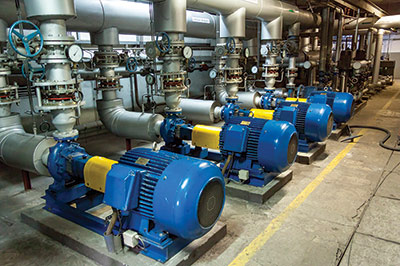
VFDs are an adjustable-speed drive used in electro-mechanical drive systems to control AC motor speed and torque by varying motor input frequency and voltage. They are used in applications ranging from small appliances to large compressors.
The variable frequency drive (VFD) cable business has become an extremely large market for cable manufactures in the last 20 years. In the past, standard AC motors had the complexity of a squirrel cage motor — just get power and it would run. The first silicon-controlled rectifier (SCR) was developed by Bell Labs/GE in 1958 to vary the speed of DC electric motors used in various applications. Since then we have seen motor speed control technology evolve from large-scale integration (LSI), gate turn-off thyristor (GTO), pulse-width modulation (PWM), insulated-gate bipolar transistor (IGBT), and space vector pulse-width modulation (SVPWM). These new forms of power conversion to support speed control in VFD motors has caused the demand on the cables to change as well, which has led to many new cable options.
- We have seen new requirements for these cables which includes:
The need for cables to support greater than 600 V (many VFDs run at 600 to 800 V), which UL addressed with the wind turbine tray cable (WTTC) 1000-V approval that not only addressed VFD issues but also the challenges of wiring a wind turbine. - Addressing reflective wave phenomenon, which could increase the voltage spike potential to as much as 1,600 V. Dealing with developing corona launch points and high potential voltage could cause heat from current between the conductor and shield, and individual conductors. Many manufacturers adopted spark-type technology, which uses rubber insulation, while others chose semi-conductive PVC/nylon to dissipate the launch points of corona and current flow.
- Providing the necessary approvals to allow customers to not only put the cable in a tray (UL TC or UL PLTC rated), but also exposed run (ER) to the panel or motor. Tray cable types TC, ITC and PLTC are permitted in cable trays by the NEC. However, if more than 6 ft (1.8 m) of cable is brought out of the tray for a connection to a motor or other electrical device, cables without an ER rating must be either armored (type MC) or be installed in conduit or some other type of raceway. In some cases, the cables are made so they are suitable as portable cordage (STO), which can be exposed for as long of a length as needed.
- Providing continuous-flex VFD cables suitable for drag chain applications.
- Providing low electromagnetic noise (EMC) internally and radiated.
- Providing low capacitance cables to provide better capacitance match to the motors and connectors.
- Providing a cable with low harmonic noise according to IEEE 519.
These requirements have been addressed by cable manufacturers but sometimes system specifications dictate additional conditions that cables must meet. The point is that one cable will not meet all the requirements listed. As an example, a customer can’t get a tray-rated, continuous-flex cable in polyurethane.
Changes in Electrical Installation Codes
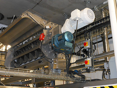
The current NFPA guidelines require RHH, RHW, RHW-2, XHH, XHHE or XHHW-2 insulation for use inside the motor’s control panel or cabinet, but the expectation is this requirement will move to include cable used in external wiring of VFD applications in the upcoming years.
A new change occurred recently in the latest revision of NFPA that cable manufacturers are currently addressing, as well as additional new alterations that may occur in NFPA 2021.
The most notable update in terms of the suitability of cables for VFD use according to NFPA 79 (2018 edition) is specifically Chapter 4 – General Operating Conditions. Currently, the general interpretation of the current 2018 NFPA for wiring amongst cable manufacturers is that Chapter 4, Article 4.4.2.8 – Circuits Supplied from Power Conversion Equipment, which requires RHH, RHW, RHW-2, XHH, XHHE or XHHW-2 insulation, is intended for inside the panel where the wiring is contained between the drives and protection equipment (of the panels) that may experience unusual overload and/or a fault condition. The reason behind this belief is because the requirement is not included in the section that applies to cable for external wiring — Chapter 12 – Conductors, Cables and Flexible Cords.
Many manufacturers are making adjustments to their VFD cable stocks in anticipation of a possible update in three years that requires the use of RHH, RHW, RHW-2, XHH, XHHW, and XHHW-2 insulation to comply with NFPA Chapter 12. Manufacturers do believe that the requirement for thermoset conductors in VFDs may be a shift in the market rather than a real concern for safety since voltage spikes, overload and inrush currents can be handled for long durations by thermoset insulation (common to RHH, RHW, RHW-2, XHH, XHHW, and XHHW-2) without premature failure, and would further be safeguarded by the circuit protection device used in the system (circuit breaker or fuses).

Select TOPFLEX and TOPSERV products from HELUKABEL have been upgraded to use XLPE conductor insulation to better serve the industrial VFD market.
XLPE and PE insulation do offer a real benefit in terms of lower capacitance ratings (as opposed to other insulation options) to better match the motor’s impedance for helping to reduce electrical issues in the system that can waste energy and increase electrical noise.
To address the continuous-flex requirement for cables used in drag chains, the use of polyurethane (PUR) jackets and thermoplastic elastomer (TPE) insulation has proven to be the best option for performance and high cycle life (over 10 million cycles). PUR jackets provide the greatest resistance to abrasion and chemicals, and also provide an elastic property to the jacket that helps hold the cable’s conductors together over a long duration of flexing along with uniform alignment to the outer part of the cable chain, which prevents the cable from moving (whipping) in the track.
Dealing with harmonics, EMI/EMC
Harmonics is another common question that arises in VFD vernacular and many of these concerns have been addressed with more noise resistant hardware in the drive units. It is still an issue that needs to be addressed because it still causes reliability issues if the proper precautions are not taken during cable installation. VFD cables are shielded with tinned copper wire braids and aluminum/Mylar foils. This construction allows the cable to have very low EMC emissions that allow them to comply with many electrical requirements like IEEE 519 and CE. IEEE 519.1 applies to the European community to help regulate the harmonics in a power system. CE’s concern is geared more towards an employee’s health due to EMI radiation and the negative effects from wireless communication.
The result of lower EMI/EMC is that the energy dissipated from the shielding is transferred to current in the shield through inductive coupling. The longer the cables are, the higher the current. Depending on how a system is grounded, these cables could allow the current to flow through the system to the point that potential voltage that is supposed to be zero volts in a drive ground is not zero. This changes the timing of the drive and causes the motors to not run at the speeds for which they are not calibrated. Most drives manufacturers require a minimum of 85% braid coverage and an independent ground system for the shield. This helps eliminate the ground loop problems found in today’s VFD drives.
Continuing changes in the VFD supply chain and products offered require that the cable industry adjust to new customer requirements in terms of both performance and regulation. Suppliers are interested in filling the needs of the customers through innovation and testing of new regulation requirements. As we see more and more electric motors replacing hydraulic and pneumatic power control in all industries, it is necessary to hone these products to provide better options from a price and performance prospective.
HELUKABEL
www.helukabel.com
Filed Under: Cables + cable management


many thanks
but I work connection between VFD and motor with xlpe cu cable 3×50 +25mm2 length around 60m
using power flex 400 from Allen Bradley compatible with line reactor and the system worked properly
please advice