By Jack Moermond, Product Specialist, Balluff, Inc. Florence, Ky.
In the field of automation, pneumatic cylinders need reliable sensors to detect piston position. Check out the pros and cons of these most widely used sensor types before you buy.
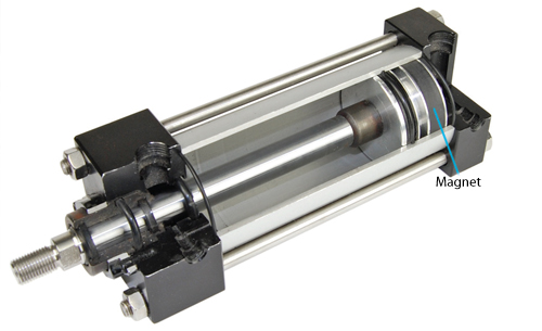
Cut-away view of a pneumatic cylinder shows a magnetic ring for energizing magnetic — field sensors.
When used as prime movers, pneumatic cylinders are durable, relatively inexpensive, and simple to apply. In order for a pneumatic cylinder to work in a control system, however, discrete sensors are needed to deliver electrical signals to a controller to report the piston’s position. One kind of sensor uses external electro-mechanical limit switches or inductive proximity switches to detect metal flags on the moving parts of the machine. The disadvantages here include the cost and complexity of the brackets and hardware, the difficulty of making adjustments, and the larger size of the overall assembly. Also, the external hardware can be damaged and misaligned during normal use or accidental impact.
A more widely used method has magnetically actuated switches or sensors mounted on the sides of the cylinder or placed in a slot on the cylinder body. Sensors can detect the magnetic field of an internal magnet on the moving piston through the aluminum wall of the pneumatic cylinder. The magnetic sensors typically detect end-of-stroke in either direction, however, multiple sensors can also detect several discrete positions along the length of a cylinder.
Reed switches:
The simplest magnetic-field sensor is a reed switch. It contains two ferromagnetic nickel and iron reed elements in an evacuated, hermetically sealed glass tube to minimize contact arcing. When an axially aligned magnet approaches the switch, its magnetic force closes the reeds. The magnet typically generates at least a 50 Gauss force to overcome the return force or spring memory of the reed elements.
Reed Switch

Reed switches are the least expensive and simplest type of magnetic field sensors. Magnets on the pistons activate the reed switches when they are in close proximity.
Reed switches are inexpensive, require no standby power, and can function with both ac and dc electrical loads. However, they are relatively slow, so they may not respond fast enough for some high-speed applications. Since the switches are mechanical devices with moving parts, they have a finite number of operating cycles before they eventually fail. Switching high-current loads can further reduce life expectancy. Also, low-cost reed switches occasionally deliver unwanted, multiple switching points as the twin lobes of certain magnets pass by. Lastly, reed switches installed in high shock and vibration applications may experience contact bounce or even physical damage. In many automated factories, hundreds of reed switches are a major source of unplanned downtime; failures can occur hourly and represent a continuous maintenance headache and lost production.
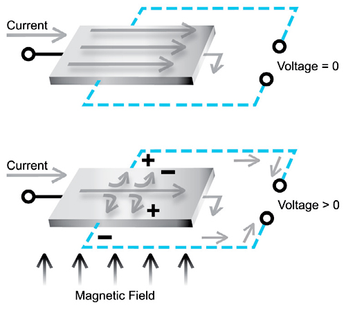
Hall-Effect sensors: Hall-Effect sensors are solid-state electronic devices. They contain a voltage amplifier and a comparator that drives a switching output. In operation, a steady dc current passes through the thin Hall-Effect chip. The electrons distribute uniformly across the element; no potential difference develops between the output terminals located on opposite sides of the chip. But, when a radially oriented magnet approaches, its field, which is perpendicular to the current vector in the Hall element, forces the electrons toward one side of the chip. This unbalance generates a µV drop across the Hall-Effect element proportional to the strength of the magnetic field. The sensor output switches on when the generated voltage reaches the comparator’s threshold.
Hall-Effect Sensor
GMR sensors comprise a ferromagnetic material that changes resistance in a magnetic field. This property lets it trigger an electronic circuit under sufficient magnetic field strength.
Since Hall-Effect sensors are electronic devices, they have no moving parts. Unlike a reed switch, their response time does not depend on magnetic forces overcoming mechanical inertia. They operate faster and resist shock and vibration better.
However, it might not always be easy to upgrade from reed switches to Hall- Effect sensors, because the magnetic field orientation of a cylinder designed for reed switches may be axial, compared to radial for a Hall-Effect sensor. So the Hall device may not operate properly when activated by an axially oriented magnet.
Furthermore, Hall-Effect sensors typically have comparatively low sensitivity; the magnetic field strength must be in the order of 30 to 60 Gauss. Some cylinder magnets designed to work with reed switches are simply not that strong. Finally, some inexpensive Hall-Effect sensors can switch twice because they detect both poles of the magnet, not just one or the other.
AMR sensors: Another type of solid-state, magnetic-field sensor is called an anisotropic magnetoresistive or AMR sensor. Its operating principle of is simple: the sensor element changes resistance in a magnetic field, which in turn, changes a bias current in the sensing element. A comparator circuit detects the change and switches the sensor’s output. Compared to Hall-Effect sensing technology, which generates a tiny µV -level signal, the magnetoresistive element responds with a more robust 3 to 4% change in bias current. This has better noise immunity and experiences less false tripping.
GMR Technology

GMR sensors comprise a ferromagnetic material that changes resistance in a magnetic field. This property lets it trigger an electronic circuit under sufficient magnetic field strength
Magnetoresistive sensors are about 200 times more responsive than a typical Hall Effect sensor to a given magnetic field strength; the practical magnetic field strength required to operate a magnetoresistive sensor can be as low as 15 Gauss. Improvements in magnetoresistive technology now let these sensors detect both axially and radially magnetized magnets.
In addition to the rugged solid-state construction, magnetoresistive sensors have better noise immunity, smaller physical size, and lower mechanical hysteresis (the difference in switch point when approaching the sensor from opposite directions). Quality manufacturers of magnetoresistive sensors have overload protection, short-circuit protection, and reverse-connection protection. Unlike Hall Effect sensors, magnetoresistive sensors do not double switch, because their higher sensitivity lets them remain in the “on” state as the low-strength portion of the magnetic field passes under the sensor. Hall-Effect sensors are less sensitive and will often “drop out” when they sense a weaker portion of a magnetic field located between two stronger areas, then switch on again when the field strength increases.
Leading magnetoresistive sensor manufacturers have developed weld-field immune versions that can operate reliably in ac welding fields as strong as 200kA/m. They are not electrically damaged nor will they generate false signals. Many of these welding sensors are available with metallic housings to further guard against hot weld spatter that would melt a plastic-bodied sensor.
GMR sensors: The most up-to-date magnetic field sensing technology is called giant magnetoresistive or GMR. Compared to AMR technology, GMR sensors have a more robust reaction to the presence of a magnetic field, at least 10%.
Due to their high sensitivity, less physical chip material is required to construct a practical GMR magnetic field sensor. So, GRM sensors can be packaged in much smaller housings for short-stroke cylinders, extremely small-bore cylinders, or miniature pneumatic grippers. Higher-quality GMR sensor manufacturers also add advanced output protection circuits such as overload protection, short-circuit protection, and reverse connection protection.
Filed Under: Factory automation, Pneumatic equipment + components, LINEAR MOTION, SENSORS, TEST & MEASUREMENT


Tell Us What You Think!