Advanced avionics and fly-by-wire systems in commercial and military aircraft are processing more data and consuming more power than ever before. That requires avionics designers to engineer embedded electronics and interconnect systems that can handle increased data speeds and bandwidth without adding significant weight. To support this goal, interconnect standards for commercial and military avionics are advancing, delivering important developments for military avionics connectors.
Importance of ARINC, IMA, and OSA Standards
Commercial airline manufacturers were the first to kick off the development of standards for aviation electronics by forming Aeronautics Radio INC (ARINC) in 1929. The initial focus was standards for ground-based communications. The scope of ARINC standards was soon enlarged to include standards for communications inside the aircraft as well.
Accompanying the development of ARINC standards were the U.S. military’s own initiatives:
- Integrated Modular Avionics (IMA): More of a concept than a standard, IMA grew out of the F-22 Joint Integrated Avionics Working Group (JIAWG) formed in 1987. The benefit for designers is that IMA allows the same part or card to be used between different computer modules, helping reduce weight and maintenance issues.
- Open Systems Architecture (OSA): The result of a 1994 Department of Defense (DoD) directive, OSA is also not a standard. It is a strategy that relies on defined and published standards-based interfaces and module designs instead of proprietary technologies. Many OSA modules are defined by standards developed by VITA working groups, such as VPX module standards for embedded systems.
While IMA and OSA share similarities, IMA is leading the future with vigorous development of standards being driven by two factors critical to avionics designers:
- Reducing weight by enabling a robust platform that puts more computing power in one box requiring far fewer nodes.
- Expanding data-transmission speed and bandwidth.
Modular Integration is Challenging
Given the evolution of standards and application requirements, military avionics designers and connector OEMs face a number of challenges.
The first challenge is to implement modular integration with a compact, lightweight packaging system that it is rugged enough for the aerospace environment. At first glance, it looks like it’s simply a matter of the OEMs leveraging COTS technologies and making them more robust.
But designing more rugged connectors can take two paths for OEMs:
- Path 1 offers the most freedom, but uses a proprietary design approach.
- Path 2 follows an OSA approach implementing open ARINC and VITA standards.
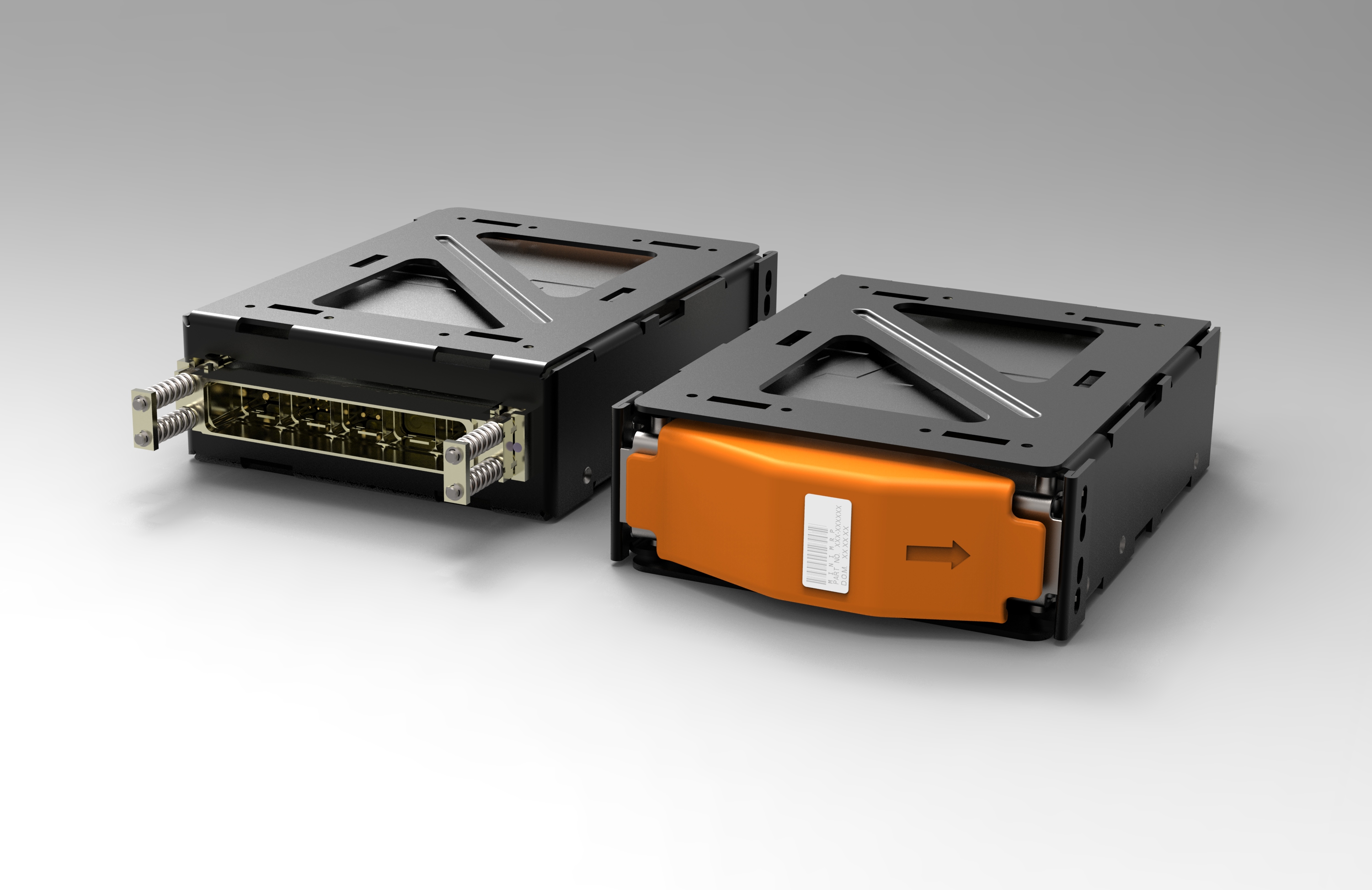
Figure 1: MiniMRP modules. (Image Source: TE Connectivity)
Boosting Bus Speed and Bandwidth Are Also Challenging
The second challenge for avionics connectors is handling increased data speeds and bandwidth. The digital battlefield is outpacing the data speed/bandwidth requirements of commercial applications. This puts more demands on box-to-box connectivity in military applications.
Fast Copper
In distributed avionics, a large number of links do not run long distances and range from 100 Mb Ethernet to 10 Gb Ethernet. In these cases, copper cabling, specifically Cat6A, is suitable for flight control, avionics, and cabin management systems. Cat6A can support 10 Gb Ethernet at 83 m, versus 36 m for a Cat 6 cable. For ruggedness, Cat6A cable is constructed with fluoropolymers that support ANSI/TIA-568-C specifications for stability in extreme conditions over long lengths and is available in 24 AWG or smaller 26 AWG to minimize size and weight.
For connectors, Cat6A cable can be terminated with ARINC high-speed connectors. They can handle the more stringent insertion loss, crosstalk, and other signal degrading factors, as well as the increased bandwidth return loss requirements that result from faster I/O. For extreme environments, circular CeeLok FAS-T and MIL-DTL-32546 qualified CeeLok FAS-X 10 GB Ethernet connectors accommodate higher speeds and smaller spaces.
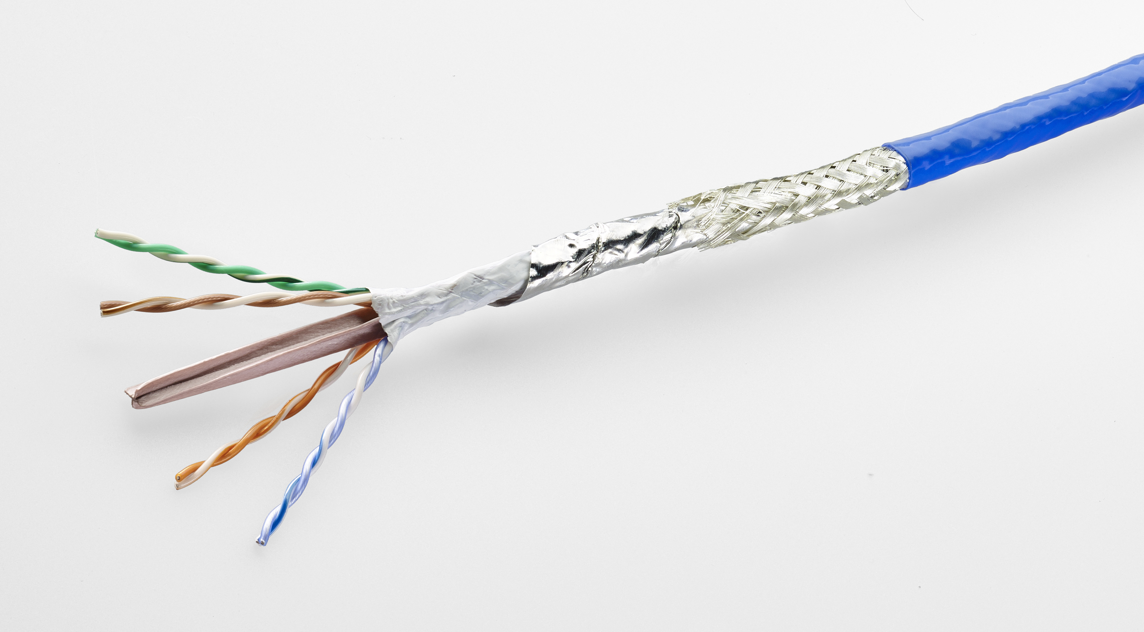
Figure 2: Cat 6a cable. (Image Source: TE Connectivity)
Figure 3: CeeLok FAS-X Connectors. (Image Source: TE Connectivity)
Fiber Optics
To provide higher speeds over longer distances, optical fiber is gaining ground in backbone applications—especially as 100G links (10, 10 Gbps fibers per Tx to Rx link) become more prevalent. The metrics clearly show the fiber-optics advantage:
- Speed and distance: A twisted pair cable can carry a 1 Gbps signal over a distance of 100 m; a multimode fiber can transmit 10 Gbps up to 550 m, and a single-mode fiber, an order of magnitude farther.
- Weight: A generic Cat6A Ethernet cable weighs 45 lb per 1,000 ft, while a fiber-optic counterpart is 78 percent lighter, weighing just 10 lb.
- Noise immunity: Optical fibers are made of dielectric materials; they neither emit nor receive EMI. Cable shielding is not required.
As military avionics systems continue to push the envelope with heavier data loads, an end-to-end fiber-optic solution is attractive. Optical fiber used to have a reputation as being fragile and hard-to-use. That’s not true now. Today’s optical fiber constructions resist crushing and pinching during installation. No-epoxy/no-polish connectors significantly speed up termination.
A relatively new component that can push heavy loads through active optical fiber networks is the video transceiver.
Future Trends
While it’s clear that many advanced interconnect products are available today, where are packaging and connectivity headed in the future?
As far as packaging is concerned, previous ARINC standards are being eclipsed by new standards, such as ARINC 836A. The same smaller sizes and higher density seen in consumer and industrial electronics are now in play for avionics. Generic packaging for aviation electronics will keep shrinking to accommodate smaller boxes and significantly lower weights. As far as connectivity is concerned, copper and fiber will continue to coexist, each lending their specific advantages.
Additional sensor processing for the digital battlefield’s Reconnaissance, Surveillance, and Target Acquisition (RSTA) tasks puts huge demands on data exchange, which will require more innovation in avionics connectivity and computing platforms.
Internet of Things (IoT) is also driving the sensor revolution. With IoT, multiple systems within the aircraft—such as engines, tires, structural components, and even seats—can self-report their status to multiple hubs to improve reliability and minimize downtime.
Filed Under: Aerospace + defense, Connectors (electrical) • crimp technologies