The variety of plastics available for ESD management is a benefit, but also a risk. Understanding the variables will make selection easier.
Tom Solon, P.E., R.H. Murphy Co., Inc.
Why are plastic materials popular for ESD management? Choices among material properties, aesthetics, and cost abound and the material can be tailored to the application. Plastics tend to be lightweight, which is helpful in automation and transportation. Most plastics are naturally insulating, allowing the addition of conductive material to create adjustable levels of electrical conductivity.

Carbon-filled materials are naturally black but some coloring is possible.
Electrostatic discharge (ESD) is the transfer of accumulated electric charge from one object to another. The transfer can cause damage. The most recognized form of ESD, the human model, results from a person becoming charged and then discharging to another object, such as an unprotected electronic component.
Another form of ESD is the charged device model, where a discharge occurs when the device being protected has a charge and makes contact with a ground path. If an electronic component has stored energy and its terminals make contact with a low resistance ground path, a rapid discharge will occur with an associated current spike. If not designed to handle the spike, internal circuitry can be damaged or destroyed. If, instead, the ground path is resistive, the discharge rate is slowed and damage avoided.
The goal of an ESD-protective material is to protect from ESD originating externally, avoid triboelectric generation, and provide a safe, regulated discharge path for any existing charge on the object being protected.
Material resistance is classified as insulating, dissipating, or conducting. Physical chemistry can explain the mechanism by which polymers and compounds can conduct electricity. But controlling the amount of conduction has relied on recipes arrived at through experimentation and empirical measurements.
A common source of confusion is use, misuse, and mix-ups of the terms surface resistivity and surface resistance. In simple form, resistivity is a basic material property while resistance is geometry-dependent and can vary with the measurement tools used. These are different measurements and it is important use them and report them correctly.
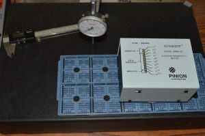
A dedicated resistivity meter improves repeatability and simplifies the process.
Surface resistivity relates to properties detected at the surface of an object. The measured units are ohms (Ω) but it is typically expressed in “ohms per square,” with “per square” being a differentiating tag and not a true element of the unit of measure. It is most easily measured on a flat surface and it is a “normalized” measurement because it can be measured with different electrode geometries and still yield the same result. More formally, it is the ratio of dc voltage drop per unit length to the surface current per unit width.
These properties make surface resistivity useful to control. It can be measured on a molded test plaque, a thin sheet, a coated surface, a thick block, or finished product. Assuming a good contact patch can be found, the geometry of the sample should not affect the measurement.
Resistivity is not a direct measurement however, so use of a surface resistivity meter, which has a dedicated electrode configuration is the easiest way to measure it. Since these meters “know” the separation and size of the electrodes used, they are able to normalize the reading. Different sample geometries may require different electrodes or meters but the readings should be the same for the same material.
Surface resistance also relates to properties at surface but, in contrast, surface resistance measurement has been shown to be electrode geometry dependent. It is defined as the ratio of a dc voltage to the current flowing between two electrodes of specified configuration that are in contact with the same side of sample under test. Surface resistance is also measured and expressed in ohms (Ω). While surface resistance may be important and relevant to a specific application, it is less useful as a material control parameter because of the additional variable of electrode geometry.
Specifications
Many characteristics define the functional electrical requirements of a material, but most are situational. Surface resistivity is useful because it is a good indicator of material performance and it can be measured readily in many configurations.
But there may be other characteristics that are worth specifying for certain applications, such as if the plastic component is used to control intentional discharge. In this case dissipation rate may be critical. Or if electrical testing of a component will be performed while in direct contact with the plastic, resistance may be as important as resistivity since it is important to make sure that conduction through the plastic will not be problematic.
When specifying resistivity, it is easiest to use the common ranges of conductive, dissipative, or insulating. These correspond respectively to <104, 104< to <1011, or >1011 ohms/square. But sometimes this will create conflicts with the material options, particularly when using carbon fiber and trying to work in the dissipative range. If the numerical specification requirements are known, it can be useful to include them rather than relying on the more generic ranges.
Testing Methods
The use of dedicated equipment for measuring resistivity, resistance, and dissipation rate is common practice. Some care must be used when selecting electrode configurations to assure that good contact occurs and measurements are made appropriately for the intended use. Many molded plastics with conductive fillers will have filler-free “skin.” Measurements made with sharp edged or pointed electrodes that can pierce the outer surface may read differently depending on the amount of pressure applied.
It is also important to use an appropriate voltage when testing. Highly resistive materials in the dissipative range can be permanently damaged from too high voltage. In an attempt to get a reading, it is tempting to increase the applied voltage but there is a risk of creating an arc within the plastic. This burns the material and creates a permanent, conductive carbon track in the plastic. Suddenly a low resistance value is obtained and the damage is done.
Practical considerations
There are several manufacturing options for conductive plastics. The manufacturing method is usually selected based on the part design and quantity. But availability of appropriate materials may be the overriding factor in making the choice.
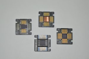
Carbon fiber bridging between leads led to the development of Isopak carriers, which use insulating material between the leads.
The two most common manufacturing methods are injection molding and profile extrusion. The choice between these two is made based on the part geometry. It is also possible to purchase stock shapes of cast, molded, or extruded material and fabricate parts as one might from metal or wood.
Recently, a few dissipative plastics have been formulated for additive manufacturing. So far only low- and mid-temp variations have been offered to the public and they use carbon powder for conductivity, which degrades the mechanical performance and cleanliness.
Part geometry can alter the material’s electrical performance. Small features may not get a normal distribution of conductive filler resulting in reduced conductivity. Or, if the features are sized similarly to the filler, individual fibers or particles can bridge the features, providing low resistance “short circuits” across the features. An example where this occurs is in test carriers for semiconductor IC chips. The carriers support and protect the electrical leads during manufacturing, using thin ribs to keep the leads straight and separated. But carbon fibers in the plastic can span the width of the ribs. This situation only creates minimal risk of electrical damage but, during functional testing, the testers can mistakenly read the leakage as a fault in the chip itself.
Color options might need to be considered. Carbon fill is the most common conductive mechanism for plastics and the default color is black. For high temperature plastics carbon may be the only option. While it is possible to color the carbon-filled materials, the color palette is limited and too much colorant can degrade the material. Lower temperature materials have additional options, including pre-colored inherently dissipative materials or the use of topical anti-static coatings on standard colored plastics.
Ultimately, the choice of filler, color and manufacturing method may be dictated by the basic polymer that can fulfill the application’s functional requirements. Here is a short list of some characteristics that should be considered:
–Temperature exposure
–Chemical exposure
–Coefficient of thermal expansion (CTE)
–Strength/stiffness
–Feature sizes
–Flame retardant or self-extinguishing requirements
Conduction in plastic materials
ESD protection relies on the ability to conduct an electrical charge. As most plastics are normally insulators, the most common way this is achieved is to add some form of carbon to the material. But the addition of carbon can reduce the effectiveness of a material’s self-extinguishing properties. Here are summaries of the different carbon forms.
Carbon Powder –this form of carbon is very fine, light, and by itself, difficult to handle.
Pros
–Relatively inexpensive – lowest cost carbon option
–Lower conductivity is easier to control– best suited to higher resistivity ranges
–Does not restrict flow much
Cons
–Dirty, powder in sufficient concentration to provide protection sloughs – It rubs off – with the associated risk of contamination – best suited to applications where cleanliness and contamination is not a concern
–Reduced mechanical strength – powder is a filler, not a reinforcement – The higher the powder content (increased conductivity), the more loss of strength
–Makes material black and limits the ability to offer in other colors
Carbon Fiber – a reinforcing element, carbon fiber is chopped to short lengths and blended into the base material.
Pros
–Increases material strength and stiffness (although stiffness may not be preferred for some applications)
–Relatively clean
–Improved wear resistance – carbon fiber reinforced materials have good wear properties because of their inherent lubricity, increased stiffness (less hysteresis heat buildup), and thermal conductivity
–High conductivity – low loading gives good conductivity
Cons
–More expensive than powder
–Greater conductivity is not well suited to high resistivity applications
–Makes material black and limits the ability to offer in other colors
–Risk of clumping when molding product with small features creating non-uniform electrical properties
Carbon Nanotubes – very small diameter tubes with very high aspect ratio (length to diameter), these are a relatively new option for conductive plastics.
Pros
–Improved control of conductivity compared to regular carbon fiber
–Relatively clean
–High conductivity
Cons
–Very expensive
–Limited availability
–Limited information
One family of plastics is characterized as Inherently (aka Intrinsically) Conductive Polymers (ICP). These copolymer plastics do not rely on a filler to achieve conductivity. They typically offer surface resistivity in the range of 109 to 1011 ohms per square. Currently they are not offered in high temperature materials. They are colorable, similarly to their non-conductive counterparts, and some grades are transparent. ICPs are considered “clean” materials because they do not have filler material that will rub or dust off. Pricing is competitive with carbon fiber reinforced materials.
For applications where low cost is most important, topical anti-static coatings may be desired. Applied to the finished product, the coating dries to leave a transparent layer. Some rely on pulling moisture out of the air and others function similarly to the Inherently Conductive Polymers. Most provide consistent surface resistivity in the dissipative range. These coatings are only on the surface and are at risk of rubbing off when subjected to abrasion and are not suitable for high temperature processing. Anecdotal evidence has shown treated parts to maintain their resistivity after 10 years in warehouse storage but these coatings are not usually considered permanent.
Finally, there are other materials that are worth watching. One is coal fly ash, a byproduct of power generation and another is graphene, a thin layer of carbon. Coal fly ash is currently offered commercially in a select group of commodity plastics. Graphene appears to still be in the investigatory stage as an ESD control additive for plastics.
Checklist
An orderly inventory of application requirements will help with decisions about materials and manufacturing processes. The more items on this checklist that can be defined, the easier it will be to make the decisions.
–Mechanical requirements – strength, stiffness, impact characteristics
–Thermal requirements – maximum temperature exposure, thermal expansion concerns
–Chemical resistance – cleaning, processing, sterilization
–Electrical conductivity range – specific needs
–Aesthetic goals – color, surface finish, transparency
–Quantities – feasible for low or high volume manufacturing
–Design volatility – how likely are design changes and revisions

Inherently Conductive Polymers are available
in special colors.
Resources
Experience should weigh heavily in your choice of suppliers. Plastic processors do not generally deal with controlling electrical properties. Techniques and controls used in ESD management are quite different than for electrical shielding. The use of carbon for ESD control involves different materials, designs, and processing than the use of carbon reinforcement for purely mechanical reasons. A good partner should be able to demonstrate knowledge and experience providing the results you seek.
References
ASTM Standard D 257-99. Standard test methods for D-C resistance or conductance of insulating materials, 1999.
ESD STM 11.11-2001 Standard. Surface resistance measurement of static dissipative planar materials, 2001.
Filed Under: Uncategorized


10°6~10°9 Matrieal for Tweezer Moulding