By Matt Connors, Application Engineering Manager, Thermacore, Inc., Lancaster, PA
Using vapor chambers can be an efficient way to manage heat in today’s small, yet high-power electronic devices where effective cooling helps ensure long component life and reliability.
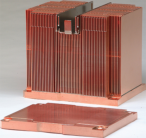
Imagine a high-power radar system used by our armed forces in the Iraqi desert. The components are engineered for top performance, but designed to be extremely compact to save space and weight. Failure is not an option for mission-critical devices like this, where hundreds of soldiers are counting on that electronic device to be the eyes and ears of the unit. These electronics must be cooled with reliable and compact systems to keep them operational even in the harshest environments.
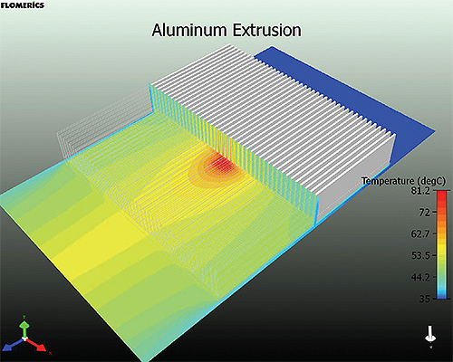
A CFD simulation for an electrical component connected to a 100-W source and its low-profile aluminum heat sink illustrates the high-temperature gradients in a cross-sectional view. The outside fins are cool compared to the hot spot directly over the component.
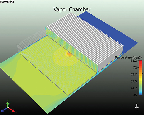
This is the same heat sink shown earlier, but has a vapor chamber integrated into its base. The heat spreads more uniformly across the sink, which drops the overall thermal resistance by 37%.
As electronic devices become smaller and more powerful, effective cooling becomes very challenging and critical for component life and reliability. The air-cooled heat sinks attached to heat-generating components must have the appropriate surface area and airflow to dissipate the heat. However, surface area alone is not enough with highly concentrated heat sources such as high-power electronic components. As the electronic components get smaller and the heat sink’s base area increases, a large thermal heat spreading penalty is typically found in the base of the heat sink. As the heat travels to the extremities of the heat sink, the cooling fins farthest away from the heat source become ineffective, so no matter how big the heat sink becomes, its thermal performance becomes constant and ineffective.
In order to show this spreading phenomenon, a CFD (computation fluid dynamics) simulation was created for a typical high-flux electrical component and its cooling sink. For this example, a 6-in. by 6-in. by 1-in. low-profile aluminum heat sink with a standard extruded pitch was used to cool an electrical component (0.5-in. by 0.5-in. source at 100 W, or 62 W/cm2). As shown, the high-temperature gradients are evident in the cross-section view. The fins toward the outside edges are quite cool compared to the hot spot directly over the electrical component. The performance of this heat sink with 300 LFM (linear feet per minute) of airflow is 0.46 °C/W, which is the temperature rise from ambient to the hottest spot on the component over the total power dissipated.
The challenge now becomes the ability to spread that heat efficiently through the base of the heat sink without changing its existing geometry. Meeting this challenge allows the designer to stay within the same form factor or original package size without a long and costly redesign of the component enclosure. In order to reduce this high thermal resistance, the heat sink metallic base needs to be replaced with a “super” conducting material. In this example, a vapor chamber can be used as the medium to spread heat in the base more efficiently.
Benefits of Vapor Chambers
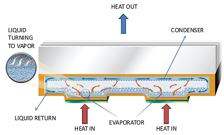
Vapor chambers are essentially flat or planar heat pipes that use the principles of evaporation and condensation to produce a very high conductivity thermal plane. Vapor chambers are basically evacuated vessels with an internal wick and a working fluid. The wick helps transport the working fluid back to the evaporator surface without using moving parts. Once the fluid evaporates, it travels to the cooler section of the chamber, condenses in the wick, and the cycle continues.
Vapor chambers can have a number of different shell materials and working fluid combinations. The selection of these materials depends mainly on the operating temperature of the cooling system. The most common combination in the electronics cooling field is copper and water due to its operating temperature of about 10°C to 250°C, but other liquids and materials can be used for extreme temperature ranges.
Bulk conductivities for vapor chambers have been measured at more than 30 times the conductivity of copper, and more than 10 times the conductivity of pyrolytic graphite and diamond in the same flat plane configuration. In addition, vapor chambers can be bonded into an existing extrusion or used as the base itself, in which case fins can be soldered directly to it. Vapor chamber sizes can range from as small as 1-in. by 1-in. to as large as 13-in. by 20-in. Standard thicknesses range from 3 to 9 mm so they can be easily inserted into existing bases.
In today’s electronic cooling market, vapor chambers are used in various applications. The military uses these high-conductivity heat sinks in cooling radar TWTs (traveling wave tubes), IGBTs (Insulated-gate bipolar transistors), and other high-flux electronics. The medical industry uses them to warm blood uniformly. A multitude of heat sinks in mid- to high-range computer servers use vapor chamber technology to manage the heat from high-flux, high-computing-power CPUs that define the speed and performance of the system.
Thermacore’s Therma-Base vapor chamber is used as the base of a heat sink to alleviate spreading resistance found in solid heat sink construction, which enables lower device temperature and greater component reliability.
To illustrate the thermal performance improvement that a vapor chamber can provide to an all-metallic heat sink, examine the same heat sink that was described earlier, but with a vapor chamber integrated into the heat sink base. As shown, the heat is spread much more evenly across the entire heat sink, causing a drop in overall thermal resistance of 37%. The heat sink shown here with an embedded vapor chamber and all of the parameters held constant exhibits a resistance of only 0.29 °C/watt.
As illustrated, the enhanced performance of the vapor chamber improves the thermal performance of an all-metallic heat sink significantly. The improved thermal performance lets the electronic component designer easily manage component frequency speed and power increases within the existing architecture, and at the same time, allows for much more computing or transmitting power for new designs in a more compact space. For example, if an electrical component in a given system is reaching its maximum junction temperature at 100 W, the vapor chamber can potentially increase the dissipated power to 130 W without changing junction temperature. This is a great advantage for devices such as high power mosfets, RF transmitters, and densely packed CPUs.
Like conventional heat sinks, vapor chambers are versatile enough to be freeze or thaw resilient and able to withstand military shock and vibration standards, but be sure to consider those variables in the specification. Operating temperature, gravity orientation, and length of power transport are all factors to account for when tailoring a vapor chamber’s internal structure for a given application. Although conventional heat sinks may be suitable for use in low power, large heat source applications, the performance of the system is limited by thermal and mechanical constraints such as heat flux, overall power, space, and mass. By comparison, the vapor chamber offers the ability to obtain the next level of speed and power in the same space.
Thermacore, Inc.
www.thermacore.com
Filed Under: Software • simulation, ELECTRONICS • ELECTRICAL


Tell Us What You Think!