The CNC bender depends on a reliable automated system for loading, aligning and clamping so that the 10-in. diameter pipe is bent precisely and consistently. The loading system experienced its motion capabilities and the influence of these CD couplings on the loads and forces. Because these systems are designed for many years of operation with little or no maintenance, every component, especially the couplings, is key to the system’s reliability and longevity.
The design challenge for the loader system of this size was to come up with a method that would ensure smooth, synchronous motion. The design configuration had to be simple enough to allow for disassembly after initial testing in the manufacturing plant, and then reassembled for actual operation in the customer’s overseas production facilities. While the actual pipe bending operation is hydraulically powered, the loading system is driven by an electrically powered Yaskawa servomotor and Stober gearbox with a reduction rate of 69.43:1. With a travel distance of 76 in., this loading system pushes, aligns and clamps tube weighing up to 1.5 tons as it progresses through the bending cycle.

Pines Technology Model 250 Heavy Duty bender automatically bends 10-in. diameter tube. It has an automated loading system powered by a servo motor/gearbox combination using Zero-Max CD® couplings to synchronize and balance the loading motion.
To handle this motion, a set of four tip-up arms in the loader isolate a single tube from the load rack and deposit it on feed rolls located at the end of each traverse arm. The four traverse arms move the tube into position for the bending machine carriage to grasp the tube. These four traverse arms must move simultaneously to transport the heavy tube to its desired position for bending.
The design engineers determined the best way to achieve this motion was using a single servomotor connected to a gearbox. The load position varied with the tube OD and bend radius so the servomotor, with help from the couplings, precisely positioned the traverse arms. CD couplings connect and span the distance from the gearbox to the traverse arms and engage with a pinion gear that engages the racks on the traverse mechanisms. Actual maximum shaft speed of the traverse mechanism was 70 rpm for a maximum linear speed of 880 in./min. The maximum motor/gearbox torque is 907 lb/in. of continuous torque.
Long-term dependability of these automated benders, and the loading system in particular, are a few of the many design features developed over the years. Pines successfully minimized wall thinning while being the first to offer a fully automatic CNC Bender designed with a vertical compression bender, hot bend titanium tubing, boost bending techniques, and a complete range of bend tooling and accessory options.

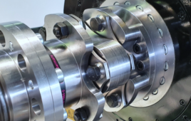
CD coupling disc pack transmits torque between shaft coupling hubs and provides high misalignment, flexibility and longer life for CD Floating Shaft Couplings compared to conventional couplings. CD couplings are proven “workhorse couplings” used in applications around the world from wind turbines to battle tanks.
Each loader uses one double flex coupling and three floating shaft couplings of various lengths. For assembly, after initial alignment and anchoring of the loader components, the floating shaft couplings are bolted in place to join the loader segments. Then, the motor/gearbox assembly is installed with the final attachments made to the coupling. At this point, the loader is test operated manually to verify that there is no binding or undue loading on the couplings.
The floating shaft coupling is a zero backlash and torsionally stiff spacer coupling. While the coupling transmits torque similar to any conventional coupling, it also handles the misalignment forces that come into play in this application. Dampening backlash and shock, without the coupling fatiguing, is accomplished by the patented open arm disc design made of highly durable composite disc material. This design absorbs and cushions misalignment forces and backlash that may occur from the servomotor’s intermittent motion. In addition, the coupling provides reliable support for the floating shaft component with very little radial load on the connected equipment and bearings.
Zero-Max
www.zero-max.com
Filed Under: Couplings

Tell Us What You Think!