Measurement applications in biomedical, semi-conductor and optical industries demand highly accurate linear stages. Typical specifications for such devices as surface-topology machines include a maximum deviation of 1 µm in position and straightness/flatness over a travel range of 100 mm or more.

Ball screw driven linear stage with decoupling mechanism.

A decoupling assembly from PMT160 stage series. A typical application for a stage with decoupling devices is high precision instruments used to measure roughness or surface topology. The addition of such a stage to a standard two-dimensional profilometric roughness measuring instrument can enhance a 3D-topography system. Instead of a single profile, a number of parallel profiles are available that can be combined in software to yield a 3D image of the object surface.
Usually, such high precision requirements are satisfied by using air-bearing stages with linear motors. Besides the basic cost and large size of such a stage, additional systems are needed to monitor air pressure and motor power to prevent damage in an emergency. These additional systems further increase cost and technical complexity.
A new decoupling system can be an alternative to air bearing systems. The decoupling system consists of classical cross roller bearings and high quality ball screws that isolates any transverse movement of the ball screw from the linear bearing system and stage saddle.
In many precision stages, the linear bearings may be dramatically oversized. Even so, the stiffness of such bearings is not infinite. Disturbance forces can elastically deform base plate, bearing and saddle, and interfere with the straightness and flatness of the whole stage system.
Disturbance forces can of course be introduced by external influences, such as the application itself. However, in most measurement operations, external forces are either minimal or non-existent.


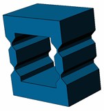
Parallelogram spring assembly — 3D, at rest, under transverse load.
Internal disturbance forces, however, are another story. One of the most important internal disturbance forces comes from eccentricity of the ball screw nut while the screw rotates. Because the stage saddle is normally directly connected to the nut, any transverse forces from it adversely affect the stage system by contributing to runout.
The new decoupling device nearly eliminates these effects through the application of flexure designs well known in piezo-micropositioning stages. Flexures do not have any play or surface friction, so wear, stick-slip and lubrication are not a concern. Even so, flexures can easily be overloaded, so thoughtful engineering is needed.
Flexures, up close
The simplest form of a flexure is a single flat spring that is fixed at one side and acted on by a force at the opposite side. It has low stiffness in bending direction but very high stiffness in shear direction (which is the same direction as the ball screw drive). Thus, the flat spring deforms from the transverse force. Not only is there lateral movement, there is also bending. Thus, the upper and lower surfaces of the spring are not parallel anymore. The flexure compensated the transverse force but the result was additional and undesirable torque.


Double parallelogram assembly — 3D, at rest, under load. This assembly only transmits actuating forces of the ball screw (high shear stiffness) and compensates any disturbance forces (low bending stiffness).
The undesirable torque can be minimized by combining two of these flat springs to form a parallelogram assembly. Now lateral compensation is possible without any detrimental torque.
The upper and lower surfaces of the assembly remain perfectly parallel. But there is a visible reduction of overall height as a side effect of the lateral displacement. In reality this effect is mostly negligible; in this example, the contraction is in the range of 10 nm.
The exact direction of the transverse force coming from the ball screw can vary. It is always orthogonal to driving direction but can be anywhere between horizontal and vertical with respect to the base plate of the stage.


Simple flat spring — 3D, at rest, and under transverse load.
Hence it is necessary to use two independent orthogonally arranged flat spring parallelogram units in a decoupled arrangement. Whatever the direction of transverse forces, this arrangement only transmits actuating forces of the ball screw (high shear stiffness) and compensates for any disturbance forces (low bending stiffness).
In a linear stage using such an arrangement, the precision linear bearing between the saddle and the base is the main component that determines straight line motion. The side mounted ball screw drive assembly includes thrust bearing, rear support bearing, coupling, and dc motor. The ball screw nut is connected to the saddle by the decoupling device.
Some ball screws have a transverse nut movement of less than 2 µm. This peak-to-peak disturbance causes a systematic periodic waviness with amplitude of 500 nm peak-to-peak or greater. For many high precision measurement applications, a wavieness of 500 nm is unacceptable.
The graph below shows flatness runout for a travel range of 50 mm for a stage without the decoupling unit. Clearly there is a sinusoidal waviness with a wavelength of 2 mm that directly matches the ball screw pitch. The measured run out is 500 nanometers peak to peak.

The graph above shows stage flatness with a decoupling unit. The previous significant waviness is almost completely gone. The remaining magnitude is less than 50 nm, which is 10 times lower than before. The dominant error is now a long period deviation over full travel which is negligible in most applications or which can easily be compensated.
The decoupling unit is assembled from parts made from spring steel, tool steel and brass. Tests with monolithic designs, where spring elements are cut by wire EDM from a solid steel block, did not yield significant performance or price advantages.
With typical deviations in straightness and flatness of 50 nm over 50 mm travel these stages represent a cost effective alternative to air bearing systems.
Steinmeyer Inc.
www.steinmeyer.com
::Design World::
Filed Under: Ballscrews • leadscrews, Couplings, Motion control • motor controls

Tell Us What You Think!