Whether you are picking a cylinder, designing a circuit, or choosing the right valve, you’ll find the help you need on the Internet.

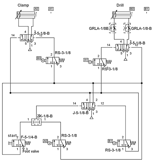
Need to create pneumatic circuit diagrams? FluidDRAW lets you work with a total of almost 700 pneumatic symbols ad more than 150 electrical symbols. Courtesy, Festo.
Most pneumatics vendors offer one or more web-based tools to simplify design. There are four major types of such tools:
• Converters
• Configurators
• CAD Drawings
• Advanced packages
Each is discussed in the following comments. It’s worth remembering that these are just examples, and that you can find different types of pneumatics design aids from many vendors in addition to those mentioned in this article.

FluidDRAW is the circuit diagram software for PCs; it operates without the use of an additional CAD system. Images created can be imported into any CAD system that accepts DXF files. Courtesy, Festo.
Converting to alternative units
One of the most common types of design aids is a simple converter program that makes for easy adjustment from metric to imperial units, and vice versa. Sounds simple, but it’s a great convenience when you are ordering scads of pneumatic components. Especially when some are specified in metric units, others in English, and all must operate in the same circuits.
Here’s what you’ll find in a typical converter program (this example, courtesy of ASCO Valve):
• Area — Square inch, feet, yards, centimeters, meters, acres
• Energy — BTU, Kilowatt/hr, watt/hr, watt/sec
• Flow — gallons/sec, gallons/min, liters/sec, cubic feet/hr, cubic centimeters/sec, cubic meters/hr
• Length — Inch, foot, yard, mile, millimeter, centimeter, meter, kilometer
• Pressure —lb/sq. in., lb/sq. ft., bar, Pascal, Kilopascal, Torr
• Temperature — degrees Fahrenheit, Kelvin, Celsius
• Velocity —ft/sec, ft/min, miles/min, cm/sec, m/sec, km/min
• Volume — pints, quarts, gallons, cubic inches, cubic yards, cubic meters, liters
• Weight — ounces, pounds, tons, grams, kilograms
Configurators for sizing, selection
Many vendors offer a powerful, web-based sizing and selection module that makes using pneumatic products even easier. Typically the configurators have the ability to assign or select a model number based on operating parameters from your data. This example (courtesy of Bimba Inc.) provides two major functional benefits:
1. Sizing module guides you through application parameters and drills down to the best product solution. It also allows direct entry of a model number, letting you evaluate the component in a set of application parameters.
2. Part number configuration. After the properly sized component is found, this module guides you through the logical creation of a model number.
This type of configurator can address three lines of questioning:
Part number known: You know the model number and want to evaluate that component under different application variables for example, how a cylinder will react if velocity is increased by X%.
General product type known: It is pre-determined by the application requirements that a certain sub-segment of products must be used. For example, a guided actuator is required, so you can select linear thrusters specifically.
Only general requirements known: A broad parametric search guides you from a general case, to a product group, then ultimately to a specific model number. For example, it may be known that a primary requirement is stainless steel due to a corrosive environment. A top-level search filters out all products meeting that requirement, from which point further sizing is performed.
CAD Models for design speed, ease
To simplify use of pneumatic components, some vendors offer 2D and 3D CAD models of their components. The models can be inserted into your designs to speed modeling and to avoid the duplication of redrawing the components. In at least one vendor offering, the CAD models are linked to a configurator so that a part model number is assigned during the modeling sequence.
Unlike the converters mentioned above, the CAD model programs vary sharply by vendor, with different approaches common. In general, though, you’ll need to download a “reader” program to allow your CAD model to be viewed through your computer. When you subsequently spell out the details of the desired model, you can download the model, view it, perform common adjustments such as rotate, pan, and zoom. And then you can take the downloaded CAD model of the pneumatic component and insert it into the assembly you are designing.
Here’s how the process is spelled out for one vendor, courtesy PHD Inc.
• Select from a large variety of Native and Neutral CAD formats including AutoCAD, Unigraphics, Solidworks, Solidedge, Catia, Pro-E, IDEAS among others.
• Native CAD formats are drawn as assemblies to allow you to use features from your CAD system to easily manipulate the geometry.
• Options and accessories like switches, shocks, and other mountings can be drawn into the CAD model.
• Request CAD models in Open/Extend or Closed/Retract positions.
• An included Configurator ensures that a proper part number is generated and handles compatibility in real-time.
• Briefcase option allows you to select multiple CAD models at one time.
• Preview configured part with selected options and accessories.
• CAD models usually generated in less than five minutes.
A PHD spokesperson notes, “The products we sell have a variety of options and our Configurator handles the compatibility. We use XML and JavaScript so all the operations happen on the client side without having to refresh the page from the server after every selection. The Configurator feeds into several different applications including sending the part numbers to our vendor to request CAD Models. We also use the Configurator for our distributors to request pricing information and to obtain an exploded view of our products to help in ordering replacement parts. In the future, we plan on integrating our Product Sizing software to feed generic part numbers into our Configurator.”
Advanced design packages
As we’ve progressed from the simplest to the more complex design aids, from converter to configurator to CAD models to design packages, each subsequent step has shown an increase in complexity and variability. And the last level, that of design packages, shows the most. At this level, you can buy a full-featured circuit design software package from a simulation firm or pneumatics company. Or you can get a simpler package that offers ease of use as a tradeoff for less flexibility. Again, here’s a specific example, courtesy of Festo USA.
FluidDRAW is Festo’s circuit diagram software for PCs, which operates without the use of an additional CAD system. Pneumatic circuit diagrams and parts lists can also be quickly created on a PC.
The comprehensive FluidDRAW symbols library accesses the extensive integrated library of DIN standard pneumatic symbols. These are arranged into groups according to drives, valves, valve terminals, compressed air preparation, vacuum technology, flow control and non-return valves, etc. Having made the section via the picture menu, you place the required symbols on the drawing in the desired position using the mouse and configure the circuit diagram. Recurring symbol combinations can be stored as macros.
From a circuit diagram to a complete parts list: The data for generating parts lists, such as the part number, product designation, etc. is available from the digital catalog. The parts list generator compiles the data and creates the corresponding total or detailed parts lists in the form of a file or a printout.
Features:
• Comprehensive, DIN standard pneumatic symbols library
• DXF export of completed circuit diagrams for further use in CAD systems
• DXF import
• Convenient print function
A total or detailed parts list can be generated for a complete overview of all pneumatic system components.

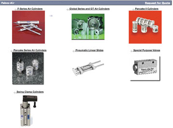
CAD models of pneumatic components can be ordered in over a dozen native and neutral 2D and 3D formats. Increasingly vendors offer the choice of downloading the drawings online or receiving them via email. Courtesy, Fabco-Air.
According to John Narup, product support engineer at Festo, FluidDRAW is simple and easy to use. “I didn’t even know we had an operating manual for FluidDRAW; I just picked it up and started to work.” Narup explains that the ISIS symbols used will import into AutoCAD or any other CAD system that accepts DXF files.
Festo also has a simulation program, FluidSIM, which uses the same symbols and works the same as FluidDRAW. FluidSIM allows simulation of a plant, and shows motion of cylinders and valves during simulated pneumatic circuit operation.
The following companies contributed to this article:
ASCO Valve Inc.–www.ascovalve.com
Bimba Mfg.Co.–www.bimba.com
Clippard Instrument Laboratory Inc.– www.clippard.com
Fabco-Air Inc.–www.fabco-air.com
Festo Inc.–www.festo.com
Nason–www.nasonptc.com
PHD Inc.–www.phdinc.com
Filed Under: Pneumatic equipment + components, ENGINEERING SOFTWARE, FLUID POWER


Tell Us What You Think!