When fasteners and threaded components such as screws and bolts are assembled with their mating parts, typical end-users make the assumption that they will fit together precisely and without any unexpected issues.
However, sometimes these components do not assemble properly if internal and external threads to not align properly. This can be a costly issue, especially if noticed during or after the machining process has begun, so ensuring the alignment of threads is critical.
Thread Misalignment
The proper rotation of screws, bolts, and threaded components with their mating parts depends largely on accurate and consistent thread alignment and engagement. The misalignment of threads can prevent part rotation and efficiency, causing mechanical issues that can lead to costly breakdowns and repairs. Some of these issues include:
Cross-threading: This occurs when the fastener does not engage properly into the mating part and seizes. Cross-threading can sometimes be remedied easily by re-engaging the parts at a different angle. However, if thread geometry is inaccurate, the parts may need to be repaired or replaced, which can be a significant expense.
Stripping: If the threads do not engage when assembled, overtightening can occur. This causes the surfaces of the threads to strip. When stripping occurs, the first step is to re-evaluate the assembly method. If stripping continues, it is often because of defects in design or machining.
Eventual Failure: If issues like cross-threading and stripping are left unfixed, threads will no longer sustain the preload, or the force created during tightening. The parts continue to wear and will eventually break down.
.JPG)
Microscope component external threads. Image credit: Vallorbs
.JPG)
Microscope component internal threads. Image credit: Vallorbs
A single fastener seizing or locking up during use or assembly may not seem like a major problem, but if a mass quantity of the same part has been manufactured for the same application, these issues can become extremely difficult, time-intensive, and expensive to repair. Despite the many issues that can occur, there are design choices that an engineer can consider that can help prevent costly misalignment in threaded parts.
Thread Geometry
Threads on a bolt or screw are characterized by their geometric dimensions. These dimensions include pitch, depth, angle, and diameter (major and minor diameters). When designing mating parts, the pitch diameter of the internal threads is typically specified to be greater than that of the external threads so they can be more easily assembled. The difference between these two pitch diameters is known as the thread fit. Fit also takes into account the measurements of the tolerances and allowances of threads.
How Important Is Fit for Your Application?
A design engineer typically specifies the fit based on factors of the application, such as operating environment, industry standards, and materials used. Fit is broken down into three classes (Classes 1, 2, and 3 defined by the Unified Thread Standard) based on precision and safety standards of the application.
- Class 1: The fit is fairly loose and is best for applications in which parts undergo frequent assembly and disassembly,
- Class 2: Known as the standard level of fit for threads. The majority of commercial and industrial screws and fasteners have Class 2 fit.
- Class 3: Highly accurate and close tolerance fits. Most often used for high-precision applications including aircraft, nuclear, or medical.
No matter the application, accurate thread geometry is a critical design element if parts are to perform and assemble as expected.
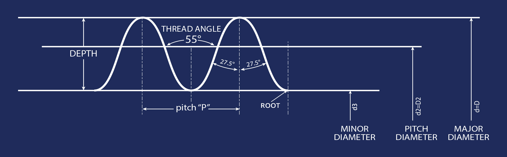
Image credit: Vallorbs
Being aware of the importance of accurate thread geometry for the application is the first step in preventing thread misalignment. However, even if a product designer has taken the time to calculate the exact thread dimensions and include them on an RFQ or design specification, issues can occur if these dimensions are inaccurately translated during machining. Depending on the capabilities and experience of the machine shop, machining methods can have a significant impact on thread alignment.
Machining Method Consistency
At this point in the specification process, the designer should understand of the importance of thread alignment in his or her application and has factored this into their measurements and design specs. In these cases, going a step further in the design process and specifying the machining method can result in end products that are not only accurate to your specs but consistently created throughout the entire production process.
Two common machining methods are thread cutting and rolling. Thread Cutting involves the use of sharpened tools that remove material to form threads. During the thread cutting, the tool edge can wear down and requires periodic sharpening throughout production runs.
.JPG)
A cut (left) and rolled comparison. Image credit: Vallorbs
Production is temporarily paused so tools can be sharpened and reset. This means the dimensions of the first thread produced are inconsistent with the dimensions of the last. Inconsistencies in geometry, even at a very small or microscopic level can cause threads to improperly engage. This is particularly critical in threads designed to comply with Class 3 fit standards that typically undergo rigorous inspection after/during production.
Thread rolling is a cold-working process in which steel dies are used to force the material outward into the shape of threads. Rolling dies are precision-ground in steel and do not wear down during production like cutting tools. This means that threading is completed accurately and consistently throughout production runs, no matter what the quantity. (Dies will wear, but much slower than conventional cutting tools)
Thread-rolling machines are not as commonly used in shops because set-up requires an experienced machine operator. To ensure accurate threading, time and testing must go into to the calibration of the rolling dies & proper blank diameter selection. Inquiring about the experience of the machine shop is a good indicator of whether they can produce accurate rolled threads that will not misalign when put into application.
Filed Under: Industrial automation