Machining? Injection molding? Additive manufacturing? Sheet metal fabrication? Engineers and product designers have several manufacturing choices to consider these days during the design and prototyping stages of making a part.
Machining and injection molding have common recommended design practices, known as Design for Manufacturing or Manufacturability (DFM), which can guide the design of a part so that it is easy to manufacture or so that it results in a better product at lower cost.
The DFM process works by simplifying a design, optimizing it, or refining it. DFM takes into consideration the limitations and capabilities of the chosen manufacturing process. For example, a designer may use an additive manufacturing process like 3D printing to prototype a design. If the choice is made to produce quantities of the part through injection molding, then DFM will analyze the design to ensure it fits the strengths and limitations of injection molding.
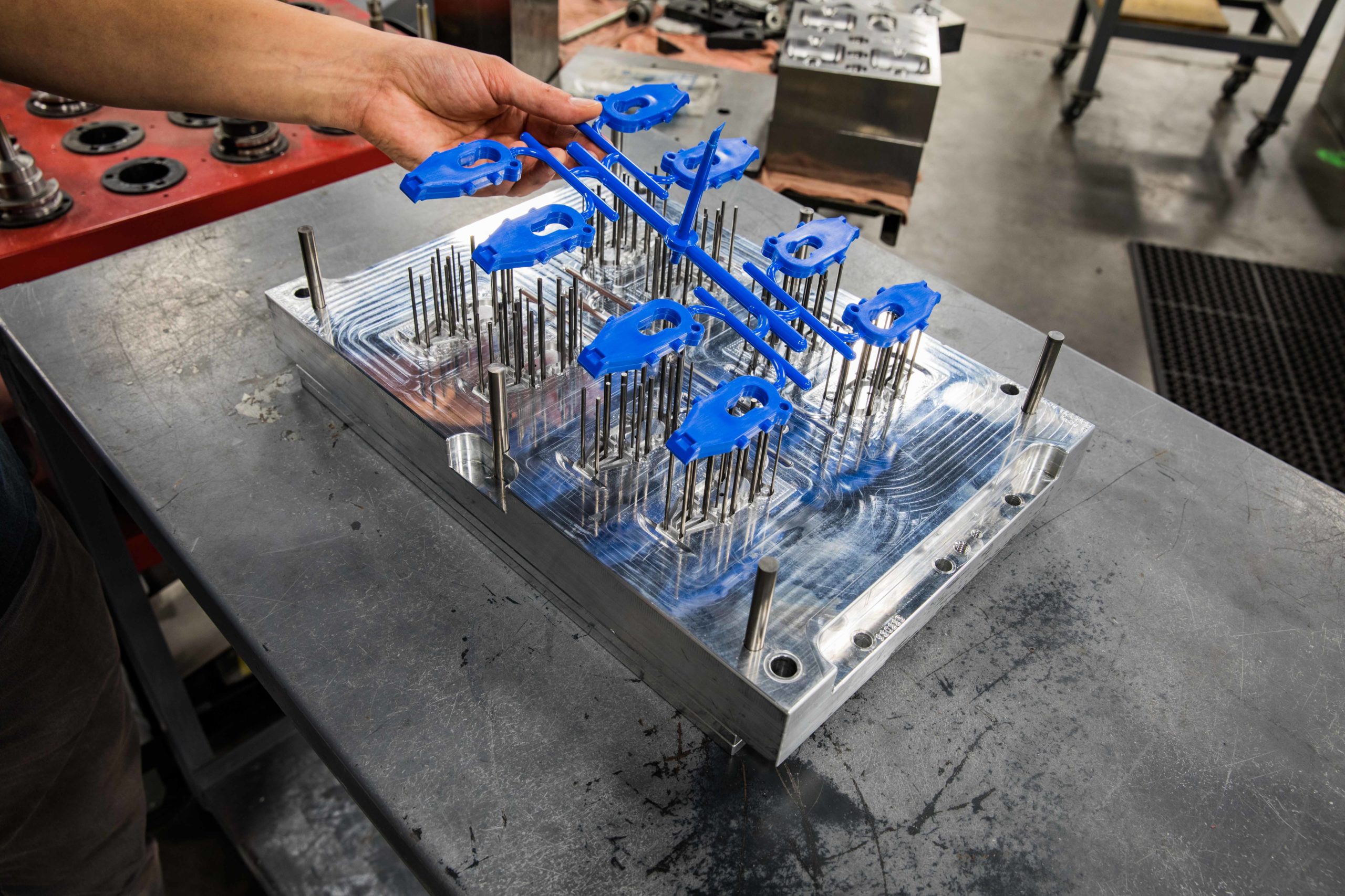
A mold with blue parts coming out via ejector pins.
Protolabs’ DFM program, for example, will show areas of thin and thick wall cross-sections or areas of the part that require draft. DFM analysis may also indicate whether new radii are needed for milling a mold, or changes that must be made to the shape of the customer’s geometry. It will show what faces should have ejector pins and what face will have a gate for filling. DFM will point out areas of risk if texture will be added to the geometry for finish and give the customer information to discuss added costs from cams, pickouts, or mold inserts due to geometry.
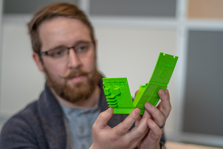
This design cube shows wall thickness, draft, radius, undercuts and other features important to consider in a design. (Protolabs offers these cubes for design use.)
The DFM recommendations and requirements are applied to the shape of the part to produce good parts from the selected method of manufacturing. Going outside the recommendations risks a range of results, from poor cosmetic features up to part failure in the application. For example, thick areas in an injection-molded part will result in sink on the external surfaces and voids within the part. In some drastic cases, the sink can actually fail completely and break into the void within the part resulting in a cavity or pocket. A sink gives a poor cosmetic appearance to the part and can often make the customer label the part “cheap plastic.” Internal porosity is another concern that can result in weakness and failure of the part for not having a solid cross-section.
To avoid such situations, designers can obtain fast feedback by uploading the existing geometry into Protolabs’ quoting software for injection molding—which includes this design analysis. The geometry will be analyzed and the analysis will show the areas that would fail, challenge, or work within the injection molding manufacturing process. Then the customer can change the geometry before submitting.

For injection molding, it is best to follow a few simple rules during the design process:
- Uniform wall thickness – change the geometry to eliminate dissimilar cross-sections that are either too thick or too thin. Injection molding requires a design that maintains a constant wall thickness.
- Draft – vertical walls, or walls that are in the direction of the mold opening and closing should be tapered.
- Radius – adding radii to the corners of the mold helps the resin to flow through the mold minimizing internal stress created by sharp corners. Sharp corners also can bite into the part as the resin cools into a solid. If the mold has an external sharp corner, that will bite or stick into the molded part harder than a vertical radius. This allows the molding company to manufacture a better part, plus they don’t have to process around sticky, or difficult-to-produce parts.
- Undercuts – parts can be 3D printed quickly without added cost from undercuts and trapped features. A part for molding may require added tooling costs for pickouts or cams that produce holds for features like power plugs, USB ports, and so on. Reviewing the mold quote with the supplier will help the designer understand where the tooling costs are coming from and if they can be reduced based on geometry optimization for the molding process.
Other common design features to watch are:
- Zero-degree draft in the direction of the mold opening and closing. This will make it difficult to create molds that produce good parts. The resin will cool and grab onto the vertical wall severely. If the molder is capable of ejecting the part, there is risk to vertical scratches on the part, pin punch stress marks where ejector pins must push harder than necessary to eject the part and higher internal stresses in the part due to process.
- Thick wall sections can result in sink and porosity, and risk excess warp due to the part cooling for a long period of time once ejected.
- Thin wall sections risk not filling the part or parts that are translucent when they should be opaque, or create difficulty when ejecting the part. The part will likely have high internal stress due to high fill pressure.
- Difficult to mold geometry, such as undercuts or trapped bodies, often require expensive mechanisms to be added to the mold or cannot be produced at all. The freedom from standard manufacturing limitations that 3D printing offers can be problematic when converting to injection molding. For example, 3D printing technically can create a hollow sphere, but if not properly designed, it can trap fluid or powder within the sphere. Injection molding would require part of the mold to produce the inner sphere and another for the outer sphere. Molding would require a minimum of 2x half spheres to mate together to produce a full sphere.
Whenever a part is shifting from manufacturing technology to another (such as 3D printing to injection molding), a review or design analysis is recommended to be sure designers/engineers are taking advantage of the new technology but not adding unnecessary cost due to the previous technology.
Protolabs
www.protolabs.com
Filed Under: Molding • injection molding components, Make Parts Fast