Temperature sensor applications usually fall into one of three general categories; monitoring, control, or circuit compensation, and four sensor types; thermocouples, thermistors, resistance-temperature detectors (RTD), and semiconductor temperature sensors. When selecting a sensor, some key characteristics to consider include temperature range, accuracy, response time, minimal temperature effect on the measured object, and the type of signal conditioning required. Other factors are long-term stability, mechanical ruggedness, and cost.
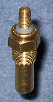
Unleaded NTC thermistor discs are frequently used in numerous automobile engine sensors to measure air and coolant temperature. The discs are located inside the tip of the housing, usually under a spring-load to maintain contact pressure.
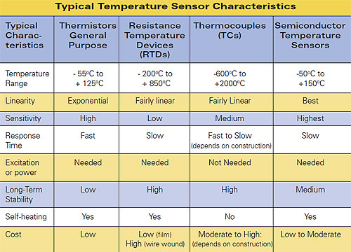
The table compares thermistor characteristics with other types of temperature sensors and shows that thermistor devices are essentially passive variable resistors and require excitation current to produce an output signal. In other words, you cannot just connect a voltmeter across the leads of a thermistor, touch the sensor to a hot object, and expect to see a voltage.
Thermistors have a considerably higher sensitivity than most other sensors, but they are also much less linear. Although special high-temperature sensors, such as chromium oxide ceramic thermistors made by GE Sensing can operate up to 1000oC, conventional devices have a relatively narrow temperature range and are not an optimal choice when long-term accuracy is required. However, thermistors are usually less expensive than the other sensors and react faster to temperature changes.
All sensors require linearization, but each to a different degree. Also, to achieve high accuracy the circuit must be calibrated with the actual thermistor sensor connected. These two tasks can be accomplished with analog conditioners and calibration circuits, but they can be quite complex and require manual calibration. If a digital design is used instead, the sensor signal is digitized by an analog-to-digital converter (ADC) and the linearization and calibration are done in software with minimum operator involvement.
Thermistor Fundamentals
Thermistors are solid-state, temperature-sensitive resistors that come in two types: negative temperature coefficient (NTC) and positive temperature coefficient (PTC). As the names imply, the resistance of an NTC thermistor is inversely proportional to temperature, whereas the resistance of a PTC thermistor is directly proportional. The sensors’ terminal resistance changes with the temperature change of the thermistor body, which can come from ambient heat, self-heating due to excitation current, or both.
PTC thermistors are used most often for circuit-overload protection, compared to NTC devices that are used primarily for temperature measurement and compensation. This article focuses on temperature measurement devices, so only NTC thermistors are discussed.
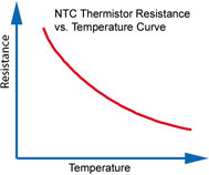
The resistance of an NTC thermistor decreases with an increase in its body temperature, however, the rate of resistance change is not linear. It is greatest at the lower temperature limit and gradually diminishes as the temperature increases.
NTC thermistors are a sintered mixture of metallic oxides, which include nickel, cobalt, manganese, and sometimes other oxides. The elements are formed as beads, chips, discs, rods, or thin-films. Bead thermistors are drops of semiconductor paste deposited on two platinum alloy wires, sintered at a high temperature. The wires are then cut to make individual thermistors. Chip and disc thermistors are fabricated as a thin sheet of material (wafer), and sintered at high temperature. The sides are silvered for attaching leads, and the wafers are cut into discs or chips. Rod thermistors are simply extruded.
Thermistor elements can be glass encapsulated, epoxy coated, or remain uncoated (bare). Bare thermistors respond faster, are smaller, and cost less, but they have no provisions for protection from the environment and mechanical impact. An epoxy coating can protect the device from the environment, but it slightly slows the response time and increases the cost. Glass encapsulation ensures a hermetic seal, high-voltage insulation, and resistance to corrosive atmospheres. Long-term stability of glass encapsulated parts is typically ten times better than the stability of epoxy coated parts.
Mounting features include unleaded discs that require spring-loaded contacts, silver or gold electrodes for wire bonding, and surface mounting provisions such as those for SMD chips. The leads can be axial or radial, bare or insulated, and straight or kinked. Axial lead and SMD parts are intended for automatic PCB insertion and pick-and-place equipment. Radial-lead devices and unleaded discs are well suited for temperature probe assemblies.

An unleaded NTC disc thermistor (a.) is commonly found in temperature probes. Adding radial leads to an uncoated disc thermistor (b.) lets it mount on a printed circuit board. Coating the disc thermistor with epoxy (c.) protects it from the environment. Epoxy-coated chip thermistors with flexible insulated leads are ideal for installations with limited space.
(Photos courtesy of GE Sensing & Inspection Technologies, Billerica, MA.)
One special type, thin-film thermistors, are deposited on a ceramic or flexible Kapton® base, only several tens of thousands of an inch thick. They have low dissipation values and fast reaction times due to their small mass. For example, TF series of thin-film NTC thermistors from Selco Products Company, are suitable for a -50oC to +90oC temperature range and have a dissipation value of 0.7 mW/oC with a thermal time constant of 2 s, both in still air. They are ideal for air and other gas temperature measurements as well as probe assemblies.
Accuracy ratings vary greatly between different devices, depending on the application. For example, general-purpose disc thermistors typically have tolerances that range from ± 20% to ± 2%, and interchangeable thermistors can have accuracies as high as ± 0.05oC in a narrow temperature range. They are available for probe replacement without system recalibration. For example, U.S. Sensor’s PR103J2 ultra-precision, interchangeable 10-kΩ thermistor is a highly accurate and stable sensor that matches the J-type NTC thermistor’s R-T curve with ± 0.05oC accuracy from 0oC to 50oC. Other resistance values from 2 kΩ to 50 kΩ are also available.
Several thermistor-related terms that are listed in catalogs and data sheets can help you select parts:
• The zero-power resistance, Ro, is a dc resistance specified at a particular temperature and an excitation current so small that the self-heating produced by power dissipation can be neglected. This special temperature is called the Standard Reference Temperature, and is typically 25oC.
• The resistance ratio characteristic is a ratio of zero-power resistance measurements made at two specific temperatures. It is typically the ratio of resistance at 25oC to the resistance at 125oC.
• The thermal time constant, τ, is the time in seconds required for a thermistor that dissipates zero power to change its body temperature 63.2% of the total temperature change in response to a step-function change in ambient temperature. This parameter characterizes the speed with which a thermistor can react to fast temperature changes and helps compare the response time of different devices.
• The dissipation constant, δ, is a ratio of the change in thermistor power dissipation to the change of thermistor body temperature. It is measured in mW/ oC and is specified at a certain temperature. Both τ and δ depend strongly on the measured object or media. For example, the dissipation constant of a GE type DC95 interchangeable chip thermistor is 8 mW/oC in stirred oil, but is only 1 mW/oC in still air. The thermal time constant is 1 second in stirred oil, but is ten times longer in still air.
• The maximum power rating is another characteristic related to power dissipation. It is the maximum power in mW at an ambient temperature of 25oC that a thermistor can dissipate for an extended period of time without degrading its characteristics. This rating must be derated based on the ambient temperature.
• The zero-power temperature coefficient of resistance (TCR), α, is the ratio of the rate of change of zero-power resistance at any temperature point, T, to the zero-power resistance at that point:
αT = 1/RT (dRT)/(dT)
Where:
αT = temperature coefficient of resistance at temperature T,
Ω / Ω / oC, or %/ oC
RT = resistance at temperature T, Ω
dRT = change of resistance, Ω
dT = change of temperature, oC
Another way to express the temperature coefficient is:
αT = – B/T2
Where:
B = material constant, oK
T = temperature, oK
Unfortunately, thermistor temperature coefficients are highly non-linear over their operating range, which means that the coefficient itself varies somewhat with temperature. A coefficient is at its highest value at its lowest temperature limit and gradually decreases as temperature increases. One value of a particular coefficient might work for a narrow temperature range, but most often, thermistor measurement circuits must be linearized to cover large temperature swings.
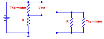
By simply adding one resistor in series with the thermistor, the output voltage vs. temperature curve can be linearized. When resistance vs. temperature linearization is desired, the resistor should be connected in parallel with the thermistor.
Circuits for linearizing thermistor outputs can be comprised of series, parallel, and series-parallel combinations of fixed resistors and additional thermistors. The simplest circuit is a parallel resistor, the value of which can be calculated from the following equation:
R = [RTM(RTL + RTH) – 2RTLRTH] / [RTL + RTH – 2RTM]
Where:
R = value of parallel resistor, Ω
RTL = thermistor resistance at the lowest temperature TL, ?
RTH = thermistor resistance at the highest temperature TH, Ω
RTM = thermistor resistance at the midpoint temperature TM, Ω
Midpoint temperature TM = (TL + TH) / 2, °C
Simple on/off temperature control circuits and applications with a narrow temperature range and relaxed accuracy requirements usually do not need linearization. A simple Wheatstone bridge circuit is usually quite adequate. Another example that does not require hardware linearization is a digital temperature circuit where the linearization is handled in software.
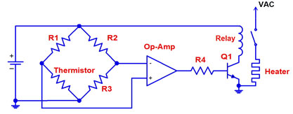
A simple on/off temperature control circuit can be designed using a thermistor in one leg of a Wheatstone bridge. Resistors R1, R2, and R3 must have a low temperature coefficient and be exactly matched to guarantee accuracy.
Operating Conditions
Certain operating conditions can significantly lower measurement accuracy or reliability and should be avoided. For instance, self-heating might become a hidden accuracy error. Thermistors generate their own heat when their excitation current is too high. The power it develops from the excitation current and its own resistance (P = I2R) can noticeably elevate the temperature of the thermistor body above the environment. Parts with a large dissipation constant, d, a low thermal resistance mounting, and other means of superior heat dissipation will have a lower temperature rise. But the primary way to avoid excessive self-heating is to keep the excitation current as low as possible.
Most measurement errors and premature failures often come from careless installation and operation. For example, although thermistors are considered to be rugged devices, take care not to crack a case, separate a bond, or exceed the upper temperature limit.
Lastly, aging is a phenomenon that is often overlooked and if not considered in the maintenance schedule, can lead to loss of calibration accuracy after extended periods of use. It manifests as an effective thermistor terminal resistance drift over time due to slowly changing resistances in the bulk material and in the contact areas between the leads and the thermistor material.
For more information:
Contact John Gyorki at the Engineering Exchange,
www.engineeringexchange.com
www.omega.com
www.gesensing.com
industrial.panasonic.com
www.murata.com
www.ussensor.com
www.vishay.com
www.selcoproducts.com
www.thermosensors.com
www.jumoplus.com
Filed Under: Sensors (temperature), TEST & MEASUREMENT


I have thermistor PTC type PTC0150000 carel with sensor KTY81/121 philips for measurement..Please advice linear voltage is possible with a series resistance (2.2 kohm)..