In the realm of ECAD, several companies have taken advantage of the SolidWorks developer program and created useful tools that make building complex electro-mechanical systems much easier.
If you’re a SolidWorks user, you know that it has really good built-in tools for electrical, hydraulic, and pneumatic routing. Or at least, you should know. The routing application is an add-in to SolidWorks Premium, and allows the creation of sub-assemblies containing paths of pipes, tubes, or electrical cables between components.
What SolidWorks doesn’t do is provide tools for the actual logical design of electrical, hydraulic, or pneumatic circuits.
Electrical and fluidic systems are often logically complex, requiring more than just the placement of a few components, wires, and tubes. These systems are generally designed in 2D schematic form, using specialized ECAD (electrical CAD) systems. Since electrical and fluidic systems have similar design philosophies, and fluidic systems are often electrically controlled, it’s becoming common for ECAD systems to support both.
The strength of ECAD systems is in logical design, not in physical design. While some ECAD systems include tools for laying out control cabinets, 2D harness formboards, and similar geometrically simple elements, these systems are no match for MCAD systems when it comes to tackling geometrically challenging tasks.
The connection between ECAD and MCAD (and SolidWorks in particular) most often comes in the realm of harnesses, wires, pipes, and hoses. In a typical scenario, logical design of these elements is done in ECAD, and physical design and optimization, including calculation of cable and segment lengths, is done in MCAD.
SolidWorks Routing uses XML based files for from/to lists, component libraries, and cable libraries, so it’s quite easy to import design data from nearly any ECAD system. Yet, the over-the-transom file-based approach to collaboration between electrical and mechanical design is often not good enough. It makes sense to look for tools that support closer collaboration between these processes.
DS SolidWorks Corp has always had an impressive third party developer program, supporting the creation of closely integrated add-on products. In the realm of ECAD, several companies have taken advantage of the SolidWorks developer program, and have created useful tools that make building complex electro-mechanical systems much easier. While each of these tools has a different take on the process of electrical design, and a different approach to integration with SolidWorks, they all provide the benefit of closer collaboration between electrical and mechanical design.
Zuken E3.WireWorks Unified
Zuken is the #2 PCB and wiring harness design vendor worldwide, after Mentor. While they may be best known for their CR-8000, CR-5000, and Cadstar PCB design software, their E3.series products for schematic, cable, panel and fluid systems design are highly regarded by engineers and designers, and are used in commercial and military/aerospace applications.
E3.WireWorks is a special bundle of the E3.series, designed to meet the needs of SolidWorks users. It’s a modular package, designed to be scalable from small applications to large. A new version, E3.WireWorks Unified, announced in February of this year, now uses native E3.series files and provides users with access to modules that were previously only available in the full E3.series.

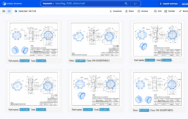
Zuken’s E3.WireWorks supports 3D wiring harness design using SolidWorks Premium Routing.
E3.WireWorks includes modules for schematic, panel, and cable design, and supports both electrical and fluidic design. It is a full stand-alone system, based on an object-oriented database. It has powerful and flexible tools for cable creation, and supports real-time design rule checking, including for short-circuits, correct wire gauge, and automatic part selection. It integrates to SolidWorks Premium Routing for harness design, and to SolidWorks Enterprise PDM for BOM management.
E3.WireWorks includes a bridge utility, which allows seamless transfer of schematic data, including to/from lists, component lists, cables, harnesses, pipes, hoses, equipment identifiers, and device ids to SolidWorks. Bi-directional cross-highlighting of equipment between the schematic and SolidWorks is also supported.
After harness routing is completed in SolidWorks, the user has the option of using SolidWorks to create a harness form-board, or exporting the cable length data back out to E3.WireWorks, to create the form-board there.
E3.WireWorks is at home in workflows where small teams of electrical engineers and mechanical engineers are working closely. But, because if its connection to the larger ecosystem of E3.series modules and Zuken PCB design tools, it’s a good choice for larger and more complex product development projects as well.
Elecworks
Elecworks, from Trace Software, is an electrical and automation CAD package specifically designed for companies using SolidWorks as their mechanical design tool. It has the distinction of being a “gold certified” SolidWorks partner product, which speaks to its integration with SolidWorks.
Elecworks Core, the main module of Elecworks, is a stand-alone application used for drawing and managing 2D schematics and wiring diagrams, managing terminals and PLCs, and editing BOMs. It supports single-line and multi-wire drawing integration, automatic generation of terminal sheets, 2D panel layout, DWG import/export, and automatic multi-language translation of projects. It uses an MS-Office style ribbon bar interface (so it will seem familiar to SolidWorks users.) It stores data in a SQL database, allowing multi-user/multi-window real-time updates.

Trace Software’s elecworks supports wiring harness and panel design, and provides full access to electrical design information within SolidWorks.
The part of Elecworks that runs inside of SolidWorks is called Elecworks for SolidWorks, and supports panel/cabinet design, as well as cable and harness design. It accesses the same SQL database as Elecworks Core, so changes in either 2D schematics or 3D models are reflected in the other immediately, requiring no import or export of data.
The panel design functionality of Elecworks for SolidWorks supports 3D part placement, including DIN rails and raceways and ducting. It includes tools for alignment of individual components, and also supports automatic placement of grouped components. It provided access to literally millions of 3D components, through the Elecworks Content portal (Trace Software are also the developers of TraceParts, one of the largest portals for 3D parts.) These components accurately reflect manufacturers’ actual parts, so component collision checks are accurate.
The Elecworks for SolidWorks routing feature uses the schematics, wires, cables, components and connection points developed in Elecworks Core, and directs the wires to channel through the most efficient route, taking into account specific characteristics required. The Elecworks routing tools allows a user to define those potential routes, priorities and segregations initially, then, using SolidWorks routing, automatically generates the wire and cable paths, updates the lengths in the wire lists, and calculates raceway fill factors. Elecworks also supports routing of pneumatic and hydraulic circuits.
Elecworks is, by design, closely tied to SolidWorks, yet it works in environments where electrical and mechanical engineers work independently. To support better project communication, it includes built in alert messaging, so engineers using either Elecworks Core or SolidWorks can communicate design changes without needing to leave their programs.
SEE Electrical Expert V4
IGE+XAO Group see themselves as developers of “electrical PLM” solutions. They support both electrical and fluidic design, and their tools are used in a broad range of applications, including commercial, military, automotive, and aerospace.
IGE+XAO are a Gold Software Partner with Dassault Systemes, supporting integrations with CATIA, Enovia, and Smarteam. They are also a solution partner with SolidWorks, providing integration of their SEE Electrical and SEE Electrical Expert products with SolidWorks Premium Routing and SolidWorks Enterprise PDM.
SEE Electrical Expert V4 is a full-function collaborative electrical CAD tool supporting schematic design, electrical equipment definition, cable definition, and terminal strip management. It is multi-user, using a database to manage conflicts, provide simultaneous access, and assure data integrity.
SEE Electrical Expert includes a number of gateways to other products, including not just SolidWorks, but also CATIA, Creo Parametric (Pro/Engineer), AutoCAD, Smarteam, Windchill, TeamCenter, and SAP. It exchanges information with PLC programming software, in order to automatically generated and update I/O card layouts, and has an optimized connection with Schneider Electric’s Unity Pro.

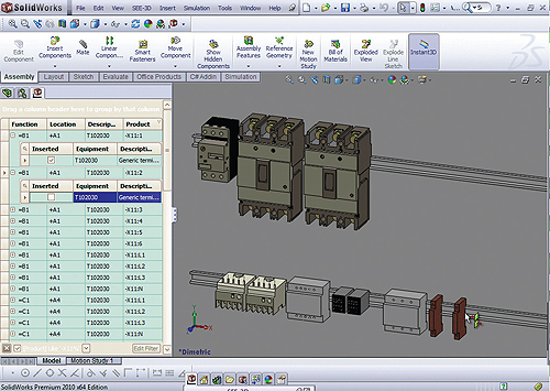
IGE+XAO’s SEE Electrical Expert V4 supports design supports design of panels and wiring harnesses within SolidWorks Premium.
The new version 4 of SEE Electrical Expert can export all project data as spreadsheets, to allow modification with Excel. This data can then imported back while managing data consistency. It is also possible to initialize a new project from an Excel file containing all the project general data (functions, locations, terminals, etc) which have been defined during the preliminary project phase.
IGE+XAO has developed a plug-in for SolidWorks Premium that supports 3D panel design. The plug-in’s “product explorer” allows users to drag-and-drop components from the SEE Electrical Expert project directly into a SolidWorks assembly, and, using smart-mates, lay out the position of those components. If a SolidWorks part corresponding to a component is not available, the plug-in dynamically generates a SolidWorks part based on the physical dimensions, number of connections, and electrical behavior defined in the SEE equipment database.
Component data used in SolidWorks is stored in the SEE project database. Changes made in either SEE Electrical Expert, or SolidWorks, such tags, component names, or even deletions, are automatically reflected in the other.
SEE Electrical Expert is likely to be a good choice in a variety of applications, but particularly in ones where its connectivity to enterprise PLM systems is an advantage.
Discuss this on The Engineering Exchange:

Zuken
www.zuken.com
Trace Software, Elecworks
www.elecworks.com
IGE+XAO Group
www.ige-xao.us
Filed Under: Software • 3D CAD, ENGINEERING SOFTWARE


Tell Us What You Think!