Edited by Zak Khan || It may seem as though linear encoders and rotary encoders have strictly defined (and maybe even mutually exclusive) applications. Prevailing logic is that linear encoders track linear motion and rotary encoders track rotating shafts — but this isn’t always the case.
Some motion designs can use linear or rotary encoders, so engineers can pick between the two. Elsewhere, designs with multiple kinds with of motion might benefit from multiple actuators on both linear and rotary axes to monitor key machine sections. Engineers should identify the locations of all potential faults of a machine and pick encoders that can detect those for the controller in some way. Some installations excel when a machine uses both linear and rotary encoders.
Example encoder application: Milling machine
Consider a milling machine that moves linearly to position itself over raw material — and rapidly rotates a drill to bore holes. Because two types of motion are present, there are two points at which an encoder can track the machine’s material removal. More after the jump.
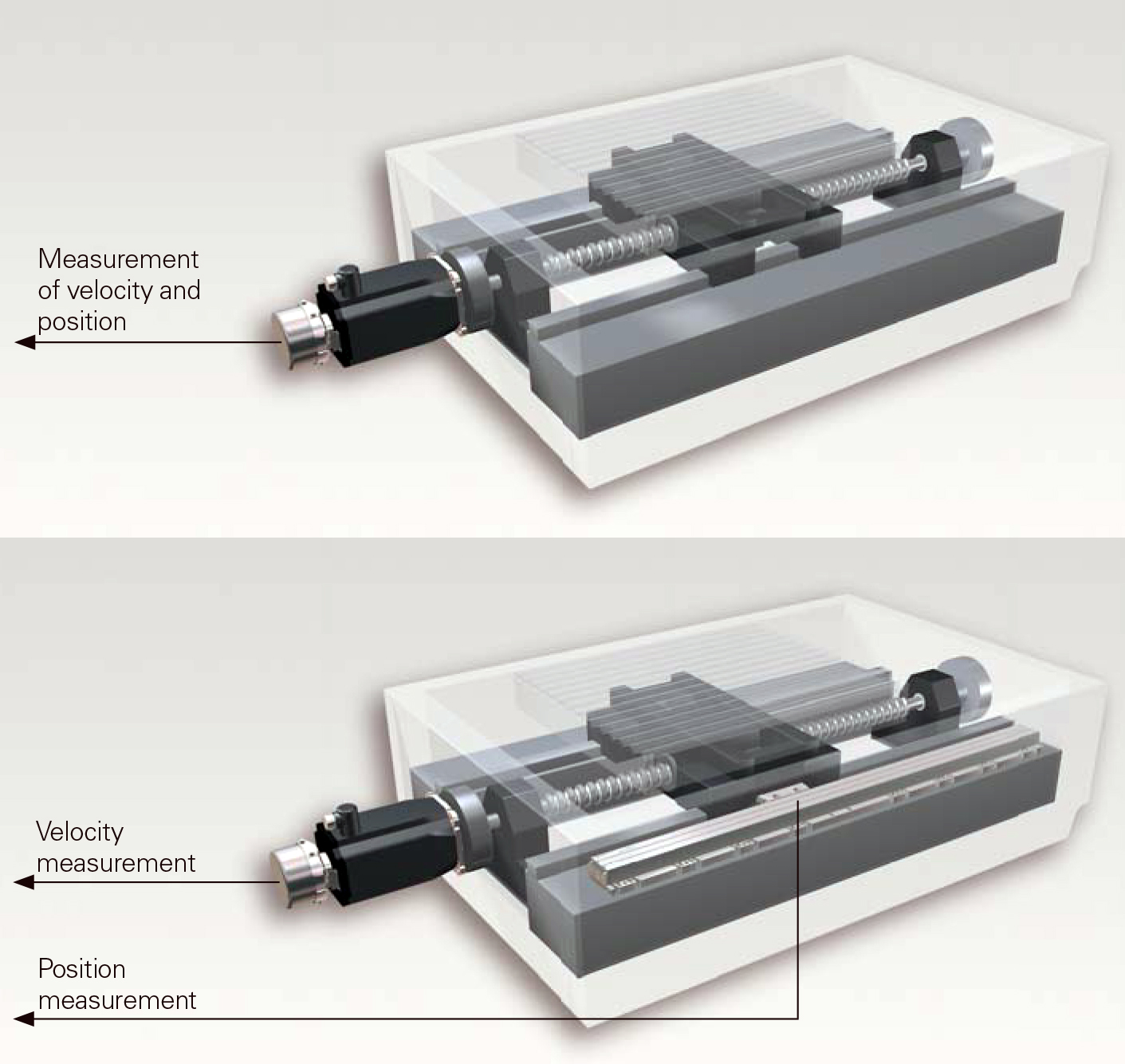
Two encoder options are to either measure output-axis motion through the ballscrew shaft with a rotary encoder or directly measure linear motion through a linear encoder. Some applications — such as a milling machine, for example — need the latter. That’s because one rotary encoder can’t compensate for thermal expansion (top image). Here, a linear encoder also helps track any displacement (bottom image). Image courtesy Heidenhain.
Using a rotary encoder means the encoder mounts on the machine’s threaded tool rod to track both linear displacement (by changes in thread pitch) and rotary position. In this particular setup, tracking rotary motion is subject to thermal drift that can cause position loss. As the machine operates, friction from material cutting heats the rod. This distorts linear position tracking because the rod expands, as the rotary encoder can’t compensate for this effect (because again, it only tracks rotary displacement and thread pitch). As these two factors don’t change with thermal effects, the encoder continues to report the same linear position.
In contrast, using a linear encoder means that the controls track the X-Y position of the drill over the raw material. Here, the linear encoder accounts for thermal expansion through measurements of linear displacement, so controls can compensate for induced errors.
Other designs where linear and rotary encoders work
Linear and rotary encoder applications overlap in other designs. Consider a conveyor belt driven by a motor. Here, a rotary encoder can track the motor even if the latter misses steps or stalls. One caveat: If the conveyor slips or breaks, the motor might continue operating as if nothing occurred.  Here, a linear encoder keeps better track of the whole conveyor system — sending feedback to the controller of conveyor motor faults as well as conveyor belt faults.
In other words …
… an application using a drive belt can use a rotary encoder on an idle roller to detect faults, as that location would let the encoder detect the ceasing of rotary motion.
In contrast, a rotary encoder mounted on the drive roller of a similarly arranged conveyor might not work so well. That’s because if the belt failed, the roller to which the encoder mounts would still spin. Here, an alternative is a linear encoder to track the conveyor to detect an loss of motion.
Thank you to Kathleen Stoneski representing Heidenhain Corp. for information in this article.
For more information, read:
Filed Under: Encoders • linear, Encoders (rotary) + resolvers, Motion Control Tips