Absolute encoders can be wired in one of three ways: in parallel, with a serial interface, or over a bus. The serial and bus interfaces have multiple protocols or standards, some of which are open-source, while others are proprietary to specific manufacturers. When considering how to wire an absolute encoder, the required resolution, level of application control, flexibility, and ease of implementation all factor into the decision.
Parallel wiring
Wiring an encoder is parallel is the most straightforward method and is the standard for single-turn encoders. In parallel wiring, the encoder is connected directly to the receiving device. Each wire handles just one data bit, which means that the more bits of resolution an encoder has, the more wires are required. For high-resolution devices, this can become burdensome and costly—particularly for multi-turn encoders, which have higher bits per turn and multiple turns.
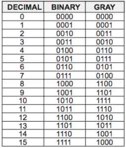
Parallel wiring often provides output in a modified version of binary code, known as reflected binary code, or Gray code (named for Frank Gray, the researcher who developed it). Standards binary code presents a problem for data transmission, because some steps involve changes in more than one bit (digit). For example, from step 3 to step 4, binary code changes from 0011 to 0100, with three bits changing state. Because it is impossible for the bits to change at exactly the same time, a false reading of the output could be taken. Gray code avoids this problem by changing only one bit at each step.
Because it uses one wire per bit, parallel wiring is best for simple implementations. Distance is also limited to less than 10 meters, due to the potential for noise interference. It is, however, a very fast communication method, with all the data available in real time, all the time.
Serial interface
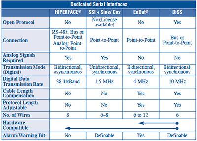
The serial wiring scheme provides point-to-point communication from a master, such as a PLC or micro controller, to a slave, which, in this case, is an encoder. There are several serial interfaces, with SSI (Synchronous Serial Interface) being the most common, particularly in Europe, while BiSS (Bidirectional Synchronous Serial Interface) is relatively new. EnDat is a proprietary interface developed by Heidenhain. The main benefit of EnDat is that it provides for internal memory in the encoder and can carry more information than SSI. Similarly, HIPERFACE is a proprietary interface developed by Max Stegmann GmbH, which provides absolute position information at start-up, and then provides incremental encoder data after that. Both BiSS and HIPERFACE can be connected either point to point or via bus. Each of these interfaces, with the exception of HIPERFACE, uses synchronous data transmission, in which the transfer of data is managed by synchronized clocks in the transmitting and receiving devices.
Serial communication is a good choice for applications with too many outputs for parallel wiring to be practical, but to few to justify a bus communication. As a benefit, serial communication works over longer distances than parallel or bus wiring schemes—sometimes over 1000 meters. However, because serial wiring schemes are point-to-point, there are limits to the number of nodes (devices) that can be included in a network.
Bus interface
A bus interface allows the encoder to communicate with other devices on the network on a peer-to-peer basis, and is also known as a ring topology. Two common bus protocols are DeviceNet and Profibus. Profibus was developed by the European Community and is, in general, more popular in Europe, while DeviceNet was developed by Allen Bradley (now part of Rockwell Automation), and is generally more common in the U.S.
Because more than one device can be connected to a single controller, bus interfaces use fewer cables than other wiring types in most applications. They also perform well over longer distances—typically up to 100 meters. However, the network topology is generally more complex, and the individual components are more expensive. Regardless of the up-front cost of a bus interface, the total cost of the system can be less than other wiring methods, due to fewer cables being required and, in turn, less setup and troubleshooting time needed.
![]()
Filed Under: Motion control • motor controls, Motion Control Tips


