By Dennis Smith, Technical Marketing Manager for Photoelectric Sensors, Banner Engineering
Intelligent fiber optic systems can satisfy performance requirements under diverse environmental conditions.
Assembly lines are faster than ever with shrinking margins for error, making the task of delivering a consistent, high-quality product both necessary and challenging. With recent advances in fiber optic sensing technology, these sensors are able to deliver more information with greater reliability than ever before. The inherent flexibility and durability of optical fibers makes them a suitable approach to a wide range of environments and applications—especially in space constrained and high sensing point density machines. Additionally, with enhanced thermal stability and faster response times, fiber optic systems deliver accurate, repeatable results. For applications from pharmaceutical packaging to small part detection, fiber optics can be mounted closely to the monitored part/object.

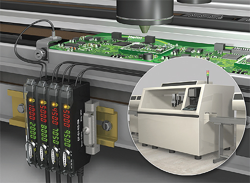
Thermally stable electronics minimize warm-up drift, enabling multiple amplifiers to be mounted closely together without heat from adjacent sensors affecting the electronics of other sensors.
Types of fiber optic systems
Fiber optics systems feature two parts: an optical fiber assembly and a remote amplifier. Optical fibers are thin, transparent strands of optical-quality glass or plastic that can be as small as a strand of hair. These fibers consist of a glass or plastic core surrounded by a layer of cladding material, which has a lower index of refraction and keeps the light in the fiber through the optical phenomenon of total internal reflection. In photoelectric sensing, these fibers are used to transmit light from the LED of the remote amplifier and return light to the photodiode of the amplifier.
Glass optical fibers are made up of a bundle of very small—usually about 0.002-in. or 50-micron diameter—glass fiber strands. A typical glass fiber optic assembly consists of several hundred fibers and is protected by a sheathing material, such as a flexible armored cable. Alternatively, plastic optical fibers can be a larger, plastic monofilament core (0.01- to 0.06-in. or 250- to 1500-micron diameter) and do not require bundling to be flexible. They are often available in a single strand of fiber optic material, but multi-strand plastic fibers improve flexibility and durability. Multi-strand plastic fibers can also be used to create an array of sensing points by spreading the fibers apart at the sensing tip.
During operation, a beam of light is transmitted through the fiber by total internal reflection. The sensing tip is non-lensed, causing the light to exit the fiber at the same approximate angle as it entered to form a cone of light.
Fiber optics offer several different assembly types, including individual-opposed, bifurcated-diffuse and through-beam array configurations. Individual-opposed fiber optic assemblies simply guide light from an emitter LED to a sensing location and from the sensing location back to a receiving photodiode. These opposed mode fiber assemblies are two separate fibers, which can be mounted far apart from each other for through-beam mode applications. Bifurcated-diffuse fiber optics transmit LED light to the target and transmit the reflected light back to the amplifier, via two branches consisting of different fibers, within one fiber optic assembly. If an object appears in front of the sensing end of a bifurcated fiber optic, light from one branch will be reflected off the object and back to the receiver through the other branch. Lastly, with through-beam array fiber optic assemblies, the fibers are spread out to form a curtain of light. This allows for detection of small objects over an area larger than possible with other fiber types.
In addition to optical fibers, these systems also contain a remote amplifier. The amplifier includes all of the electronics for the system, and is responsible for transmitting LED light and measuring the amount of received light. For quick-reference feedback, the amplifier provides a visual readout of the received light level as well as the current switch point threshold. The microprocessor compares the received light level to the switch point threshold and adjusts the output as necessary based on the light operate or dark operate state defined by the user. Light operate means the output is conducting when the received light level is greater than the switch point threshold. To accommodate high-speed processes and detect small targets, the microprocessor is capable of output switching times as fast as 50 microseconds are possible. The optimal electronic gain level is automatically selected by the microprocessor to produce a stable and robust signal from the target, which won’t saturate the amplifiers—enabling detection of small changes in received light level, also called low contrast applications.

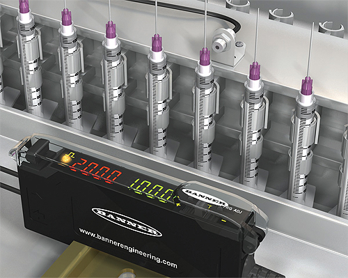
Fiber amplifiers automatically determine the optimal sensitivity necessary for each applications, making them ideal for small object detection, like syringes.
Setup and applications
With the amplifier’s simple, menu-driven set-up, installing and configuring fiber optics systems should be relatively intuitive. Advanced fiber optic amplifiers generally offer multiple “teach or set” methods, featuring traditional 2-point teach methods and innovative 1-point set methods for easy set-up and application performance—enabling optimal gain and threshold for all applications. However, even with the powerful “teach and set” methods, users can still control the entire system by manually setting and altering all performance parameters as necessary.
Because it contains two parts, fiber optic systems enable sensing in remote or difficult environments. In applications where sensing space is limited, the small fiber assembly sensing tips—ranging from 2.5 to 6 mm—and their flexible fiber enables them to be routed in and around machines where other sensor solutions cannot fit. This allows the fibers to be mounted in close proximity to the target and inside the machine, while the amplifier is mounted remotely in a user-accessible location. This protects the amplifier from damage, while providing easy viewing of operating parameters on the displays and access to the teach buttons. The remote operation capabilities are also beneficial in environments subjected to extreme shock or vibration, where a robust fiber assembly can be mounted in the challenging environment, while the sensitive electronics are mounted is a control cabinet or similar type location.
Fiber optics can also accommodate high and low contrast applications. Due to their electronic gain control and precise thresholds, the system can detect low-contrast or long-range targets. Their increased thermal stability enables fiber optic sensors to identify low-contrast targets reliably over ambient temperature changes. Plus, to accommodate constant demands for improved energy efficiency, some advanced fiber optic sensors offer an economy display mode. When enabling this feature, users can reduce the amplifier’s power consumption by up to 25%. The display is dimmer than in regular mode but still readable.
Continuing advancements in electronic technology and design practices allow improved thermal stability and reduced warm-up drift. Warm-up drift is a phenomenon that occurs while the amplifier electronics heats-up during initial power up, causing fluctuations in the amplifier gain stages, resulting in changes to the light signal readings as the electronics warm-up. Minimizing warm-up drift allows users to power-up their machines to operational condition faster, while the thermal stability enables installation of several amplifiers side-by-side, without the heat from the adjacent sensors affecting the electronics of other sensors. The high-speed electronics and specialized firmware algorithms include crosstalk avoidance, so multiple fiber assemblies can be mounted in close proximity. Crosstalk occurs when multiple fiber assemblies are mounted close together, sensing different parts of a single target, where one fiber might “see” the light of another. To prevent false detection, crosstalk avoidance allows a sensor to randomly shift its LED-firing pattern to avoid overlapping signals from other fiber amplifiers.
Fiber optics in action
Fiber assemblies can be used to detect syringes in automated assembly processes. Today, the assembly and packaging of syringes has become a fully-automated process to avoid contamination from handling. As the parts move down the rail, reliable detection is needed in order to sense and count the small components that make up the syringe, even though syringes are prone to swinging and vibrating through the sensing field. For this application, a fiber amplifier and fiber assembly is suitable because optimal sensitivity is automatically determined to detect the small translucent objects or the thin needle—and the sensor performs flawlessly even when it moves and sways along the rail.
Another common application of fiber optic systems is for reliable small part counting. In pharmaceutical bottling filling applications, it is necessary to quickly and accurately count small pills, tablets and gel caps to ensure that the bottles are filled with the correct amount. Since the exact location of the pills vary as they drop, a fiber optic array which spreads the light over an area, paired with a stable sensing amplifier with precise thresholds ensures accuracy in this type of application. Specially-designed, preconfigured fiber optic arrays make alignment of the fiber array and object being counted less critical than when using single point emitter and receiver fiber optic assemblies. This assures reliable, consistent small object counting. However, since gel-caps are translucent, the sensor may see the single object as two objects resulting in a double count. Therefore, sensors equipped with a variable off-delay or dynamic event stretcher can increase the duration of a detection event by a user-configurable percentage, counting the gel cap only once as it passes through the fiber optic array.
Banner Engineering Corp.
www.bannerengineering.com
::Design World::
Filed Under: Factory automation, SENSORS, TEST & MEASUREMENT


Tell Us What You Think!