One of the standard indications of a nearby UFO is the sudden failure of all electrical components: your cellphone no longer operates and your car coasts to a stop, often on an isolated country road late at night. You glance out of the window to see a plane falling out of the sky. Clearly, an EMP attack of some kind is underway. Societal collapse is imminent, as the unfortunate sailors in Figure 1 no doubt discovered. Not sure why it didn’t make the news: the US election, I expect.
Luckily for air travel (and the future of our planet), manufacturers of military and aviation electronics are well aware of the risks posed by both alien invaders and more mundane sources such as lightning strikes, solar flares, high-power radio transmitters, ESD, and so on.
Depending on the frequency spectrum of the interference and the coupling mechanism designers use multiple approaches to mitigate EMC effects, including careful PCB layout, grounding, shielding, and filtering. For reducing conducted interference entering a module, stopping the noise at the point of entry—the connector—is a very effective approach.
A filter connector adds EMI/RFI suppression components to a standard connector form factor to help solve EMC problems. This approach contains the filter elements within the connector itself, maximizing functional PCB area and saving weight compared to the alternative approach: a standard connector plus a PCB-mounted filter.
Electrically, a filter connector has several advantages. Its metallic shell and ground plate provide a minimum impedance to ground and higher performance than a PCB-mounted filter, and provides more consistent pin-to-pin performance.
Filter Connector Construction
Externally, a filter connector looks like the standard version, but embeds capacitors, ferrite inductors, and other components into the connector body.
Capacitor Options
Three types of capacitors are commonly used: a standard ceramic chip capacitor embedded into the connector body; a tubular ceramic capacitor around the body of the connector pin; and a planar capacitor array for multiple pins. Figure 2 shows the latter two types.
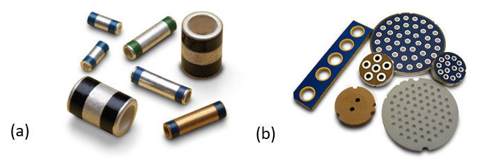
Figure 2: (a) Tubular and (b) planar array capacitors. (Image Source: API Technologies)
A planar capacitor array is a barium-titanate ceramic disc or rectangle that provides a common substrate for a capacitor on each line of a connector. The capacitance values can range from 500 pF to 0.1 μF, and different values can be combined in the same array. The capacitor array also provides a continuous ground plane across the interface of the connector.
Inductor Options
The inductor packaging options are similar: a ferrite bead around the connector pin, or a ferrite slab which all the pins pass through. Ferrite beads can provide inductance of 0.5 uH to 5 uH, along with 10-100Ω in the equivalent circuit.
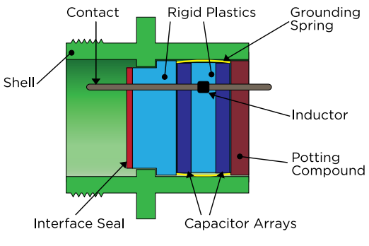
Figure 3: Arrangement of components for a Pi filter. (Image Source: TE Connectivity)
Figure 3 shows the arrangement of components for a Pi filter, which requires two planar capacitor arrays. The planar array provides the ground path for each capacitor; a compliant grounding spring connects the array to the connector shell.
Other Component Options
Filter connector designs may be optimized for a wide range of application environments: Features can include: different capacitance values on individual lines; transient voltage suppression (TVS) diodes; Metal oxide varistors (MOVs); grounded holes and feedthroughs; and customer-defined filter architectures. Both surface mount and leaded components can be added: the Glenair connector in Figure 4 uses a small PCB to add leaded clamping diodes to the design.
Manufacturers also offer mechanical packaging options, including hermetic sealing and hybrid fiber optic/electrical connectors; PCN mounting; and crimped contacts.
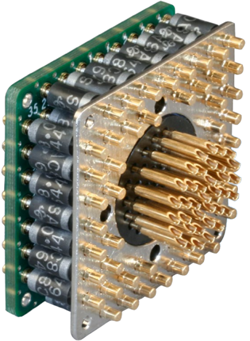
Figure 4: Any shape of connector can incorporate filter elements. (Image Source: Glenair)
A connector can include a variety of filter topologies, as shown in Figure 5. A single capacitor inserted between the signal line and ground is the simplest and lowest cost option, and has good low-frequency performance; the performance of LC-type filters is excellent if the source impedance is less that the load impedance.
A connector can incorporate more sophisticated filters by stacking planar arrays. For example, the Pi filter is popular in MF, VHF, and UHF applications since it has a steep insertion loss curve for frequencies above 10 Mz. TE Connectivity’s Deutsch filter connector family even includes a double-T filter option with three inductors and two capacitors.
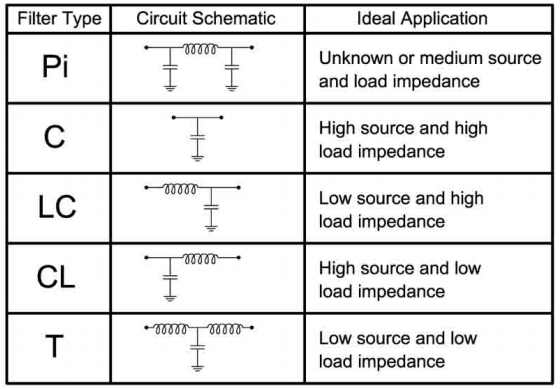
Figure 5: Filters for different combinations of low (<10Ω) and high (>100Ω) source and load impedances. (Image Source: EMP Connectors)
Insertion Loss
Whenever a component such as a connector is inserted into the signal path between source and destination, it causes a degradation of the signal: insertion loss (expressed in dB) is a measure of this degradation.
A filter connector’s job is to remove unwanted noise, but in doing so it may also attenuate a portion of the desired signal. It’s important to minimize insertion loss over the frequency range of interest: even though the post-connector signal can be amplified, too large an insertion loss may result in an unacceptable degradation of system performance. Each filter type has a characteristic insertion loss over the target frequency range, as shown in Figure 6.
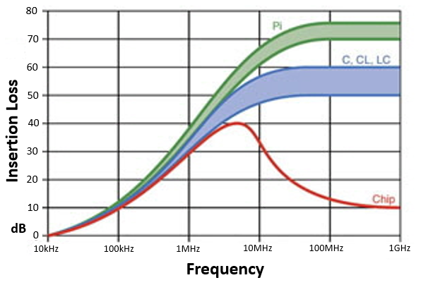
Figure 6: Comparison of insertion losses for different filter types. (Image Source: Connect Solutions)
Retrofit Solutions
Specifying a filter connector from the start of the project may be preferred, but its increased cost may preclude use in many applications. If EMC problems occur in the field, a retrofit solution may be the answer. Quell, for example, offers versions of its EESeal filter insert for numerous connectors, including circular MIL-C-26482, MIL-C-38999, MIL-C-5015, MIL-C-83723 connectors, plus ARINC, DIN, subminiature D, and custom designs. The technology limits fast transients by embedding discrete filter components in an elastomeric shell; the component connects between the pin and the outer edge of the insert, which shorts to the connector shell ground. Capacitors up to 1μF, resistors, MOVs, and diodes are available; some models can include more than one component per pin.
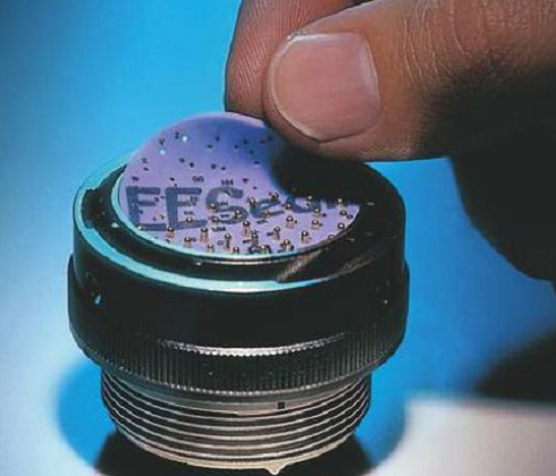
Figure 7: Installing an EESeal elastomeric filter. (Image Source: Yumpu/EESeal)
Conclusion
The military and the avionics industry are both major users of filter connectors, so circular MIL-STD and ARINC connectors constitute the bulk of most product catalogs. Both customers use filtered connectors to ensure the reliable operation of communication and navigation equipment; the military must also protect both its aircraft and ground vehicles against EMP attacks.
Let’s hope the aliens don’t have photon torpedoes.
Filed Under: Aerospace + defense, Capacitors, Connectors (electrical) • crimp technologies