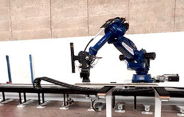
Pneumatic grippers still dominate robotic and industrial-assembly applications. That’s because pneumatic grippers are reliable, come in myriad sizes, grip quickly, and produce considerably more force than similarly sized electric grippers.
Peter Farkas, president of AGI
They’re also less expensive and simple to control, according to Peter Farkas, president of American Grippers Inc. (AGI).
“Pneumatic grippers are the most common end-effector type in everything from industrial production to cleanroom environments … mostly because they’re compact, lightweight, and offer a high force-to-weight ratio to benefit high-speed assembly machines,” said Farkas.
Designers can adjust gripping force using a regulator (in the form of a filter regulator lubricator or FRL) and control speed via metering outflow controls. They can also stall pneumatic grippers in any position indefinitely without risk of overheating (like electric units). In fact, the grippers don’t need rest periods between actuation, so have unlimited duty cycles.
But what should design engineers know when specifying and using pneumatic grippers?
To answer that question, the following is the full commentary from edited comments provided by Farkas for our recent article, Quiet evolution in industrial grippers and end effectors.
Farkas has been president of AGI Automation Components since 1997. His company (headquartered in Trumbull, Conn.) manufactures myriad pneumatic components for industrial automation.
Standard grippers come in parallel and angular types. Parallel grippers are common, due to their ease of tooling and adaptability to various part sizes without forcing users to change the tooling finger. They’re also suitable for synchronous use (where both jaws move at the same time) or non-synchronous use (where the jaws comply and shift to the workpiece centerline).
In contrast, angular pneumatic grippers have a jaw that moves in relation to the gripper body. Angular gripper jaws swing in an arc that can be adjusted to reduce the opening swing; usually they are dedicated to picking up one size part. These grippers are useful for applications with limited vertical space and the need for fail-safe part handling. Once the jaws are two degrees past parallel, toggles lock to firmly hold the part … even in the event of air-pressure loss.
No matter the type, here are five ways to increase pneumatic-gripper reliability.
1. Minimize tooling finger length and weight. Longer tooling will deflect as well as put excessive moment torque on bearing, increasing friction and reducing gripping force.
2. Build in compliance to reduce stress on the actuator and machine.
3. Design in smooth deceleration and acceleration via programming or shock absorbers.
4. Design tooling fingers with an encompassing grip for a secure and precise placement of the part.
5. Never use WD-40 (short for water displacement, 40th formula) on grippers. It’s a penetrating oil with very low viscosity that will cause seal and bearing failure.
Next, here are some tips to increase productivity.
• Design tooling jaws to limit space between the tooling jaws and work piece; this improves the cycle time of actuation.
• Select the proper material for tooling jaws to prevent deflection; look up the coefficient of friction between the work piece and tooling to prevent slippage.
• Use a lockout regulator to prevent tampering of air pressure and avoid damaging the part being handled.
• Realign the gripper to the work piece after changing venders or molds since the tolerance may be different, causing jams or crashes.
• Use a standard off-the-shelf gripper; custom units will halt production until a new one is manufactured.
For more information on gripper trends and designs …
Gripper trends feature: Quiet evolution in industrial grippers and end effectors
Design World’s library of pneumatic-gripper stories on pneumatictips.com
The post Five ways to get the most out of pneumatic grippers appeared first on Robotic Tips.
Filed Under: Actuators, Bearings, Pneumatic equipment + components, Robotics • robotic grippers • end effectors