By Gary Kirckof, PE, Applications Engineer, Beckhoff Automation, Burnsville, Minn.
Consider these tips when optimizing flying shear motion applications.
The term “flying shear” refers to general applications where the work performed by some type of tooling must be done on a moving target. At the beginning of a machine cycle, the tooling must reach a synchronized position on the moving target and track this position while the work is performed. Common flying shear applications include cutting, printing, and embossing a moving web. An example is heat sealing two plastic webs together while the webs are moving, which is common in blister pack manufacturing.
This example starts with a web of plastic packaging material. Pockets are previously formed into the web and product placed into the pockets. Another web of material, traveling on top, will secure the product in the pockets. The product will be held in airtight chambers to preserve the quality of the product after both webs are sealed together. A heated platen is used to create the seal by pressing both webs together. The temperature of the platen, the amount of seal force, and the contact time determines the quality of the seal. This assumes that the pattern machined into the platen aligns with the corresponding pattern on the webs. It also assumes that the platen doesn’t move relative to the web during sealing.
The motion of the seal platen is important to the seal quality and is divided into three phases. The first is referred to as the synchronization phase. In this phase the seal platen starts from rest and ends moving at constant velocity with the platen speed and position matching that of the web. The platen must accelerate up to speed while at the same time move the appropriate distance in order to align itself with the pattern on the web. The second phase is the tracking phase because the platen must maintain its alignment with the web so it can contact and seal the web. The amount of time the platen must stay in this phase is determined by the required seal time. The last phase is the return phase where the platen decelerates to a stop then returns to its starting position. All three phases must occur within one machine cycle.
It helps to think of the web as segmented into lengths where each length represents one machine cycle and typically one group of product. A group of product here is referred to as a blister pack. It can also represent multiple blister packs depending on the width of the web. The seal platen needs to know where the blister packs are so it can move the appropriate distance during the synchronization phase. This dictates that the web must be registered, which means that the position of the web is synchronized with the position of the nip roller. Most webs are pulled through the machine using nip rollers and the position of these rollers is used to report the position of the web. The length of web representing one machine cycle can be indicated as a nip roller position from 0 to 360 degrees. The web is registered to the nip rollers either through setup procedures, registration correction moves, or by the die-set that forms the pockets in the web.
The seal platen motor is electrically coupled to the nip roller motor, making the position of the seal platen linked to the position of the nip rollers.
The tracking phase is determined by the required seal time, which leaves the remaining time for synchronization and return. Most of the motor torque is consumed when accelerating or decelerating and only a little is used to overcome friction. This means that the peak torque demands of the motor will be determined by the synchronization and return phases. The RMS continuous torque demand is determined by the overall cycle.
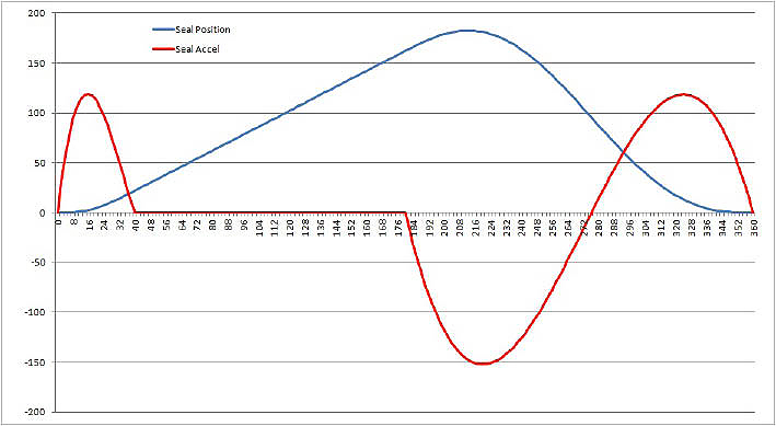
The graph illustrates an optimized flying shear motion application. The graph shows that the tracking phase takes place between 40 and 180 degrees. Both the platen and the web travel at the same speed between these two points as represented by the straight line. The required seal time is represented by the difference between these two points by factoring in the web speed and the scale factor of cycle length per 360 degrees.
For instance, if the synchronization phase is given just a little time, this results in the acceleration rate and thus the required motor toque being large during this phase compared to the return phase. Likewise, favoring the synchronization phase by cutting the return time will result in a large return phase acceleration rate. The trick to optimizing the complete motion of the seal platen is to balance the time in the synchronization and return phases so that their acceleration rates are the same. Balancing synchronization and return phases results in the lowest acceleration rate and thus the smallest motor possible, saving costs while reducing engineering efforts as well as wear and tear on motors.
Flying Shear Solutions
PC-based software solutions have made it easier to implement a range of motion applications, including flying shear applications. For instance, Beckhoff’s TwinCAT automation software suite offers a collection of motion and camming software libraries.
Specifically, a PC-based controller can deliver the processing power required to capably handle flying shear applications. In hardware terms, this could be in the form of a cabinet mounted industrial PC (IPC), panel PC with integrated display, or a DIN-rail mounted embedded PC. This hardware would be paired with TwinCAT motion control software.
For system networking, an advanced and deterministic industrial Ethernet protocol with dynamics for motion should be considered. For applications like flying shear, EtherCAT is a good drive and I/O bus for a number of reasons. It makes it possible to distribute the servo drives closer to the motion axes in the application. This arrangement means shorter power and resolver cable runs from the drives to the motors, greatly reducing infrastructure costs. Beyond simplified cabling, EtherCAT also enhances performance for many motion control applications. For instance, it’s possible to communicate with 100 servo axes every 100 microseconds. With this cycle time, all axes are provided with set values and control data and report their actual position and status. Also, the distributed clock technique enables the axes to be synchronized with a jitter of significantly less than 1 µs.
Discuss this on The Engineering Exchange:

Beckhoff Automation
www.beckhoffautomation.com
Filed Under: AUTOMATION, MECHANICAL POWER TRANSMISSION, Motion control • motor controls, PCs

Tell Us What You Think!