Ford Motor Co. design engineers are using immersive engineering to design better components and release them to production and assembly sooner. At the same time, assembly and installation problems with components have fallen by 80%, measured as a new vehicle goes into production.
MOTION-TRACKING AND–ANALYSIS AT WORK:Suited up for motiontracking and –analysis, Allison Stephens, Ford technical specialist in erogonmics, ensures there will be no snags with the installation of a new underhood component as a new vehicle goes into production. She manages the Dearborn (Mich.) Ergonomics Laboratory.
Image courtesy of Ford Motor Co.
The gains stem from marrying motion-tracking and motion–analysis technology with ergonomics, making them part of Ford’s virtual manufacturing toolset. This form of immersive engineering and collaboration between design and assembly is helping Ford carve one year out of the time needed to move new vehicles from design inception to production.
The virtual manufacturing toolset includes the Digital Buck, the multi-gigabyte 3D visualization Ford builds of every new model. This model includes all of the vehicle’s thousands of components, each one added as soon as its design is released. This virtual world includes a Virtual Center in Dearborn, Mich., a large theater-like room with three whiteboard screens for displaying engineering data and analyses.
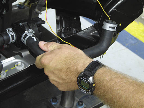
DESIGNED TO FIT: Coolant hose being installed on a coolant pump – as designed—on a Ford Motor Co. vehicle assembly line. Motion-tracking and -analysis for ergonomics, combined with DFMA, ensure that every component like thiswill go into its correct place under the hood on the first try.
The teams in the Virtual Center change constantly, but they develop better sets of constraints—component dimensions plus clearances for fittings, hands, and necessary tools. As design guidelines, constraints determine how quickly and how well a component will be installed on the assembly line.
Jeffrey P. Luther is a fluid transport specialist for cars and light trucks and designs and routes synthetic rubber hoses, “which never go in a straight line, even to and from the radiator.” He provides assembly engineers in Ford Vehicle Operations with data about each hose—length, diameter, bend radii and clamps, fasteners, hand and tool clearances, and the physical exertion required.

GRAPHING THE GAINS at FORD: This chart shows dramatic drop in component installation problems at vehicle launch by model year. The raw numbers fell from 578 to 72 in five model years, or more than 85%. Chart is from Ford Motor Co.’s Automated Issue Management System.
An essential part of developing the design constraints at Ford is ergonomics. For Luther that is the exertion effort needed to attach a hose end onto its fitting. These exertion standards are developed with a combined motion-tracking and human performance analysis system. This system includes ergonimic analysis software from Siemens PLM Software Inc. and a motion tracing sytem from Motion Analysis Corp. that is comprised of 15 digital cameras and software to reconcile overlapping images in real time. It is installed in Ford’s Ergonomics Lab in Dearborn, Mich. With the immersive engineering and integrated ergonomics in the virtual manufacturing toolset, Ford has moved Design for Manufacturing and Assembly (DFMA) upstream.
“Thanks to the virtual manufacturing toolset, we have had an 80% reduction in manufacturing issues overall during launches,” says Allison Stephens, technical specialist in assembly ergonomics. “Partly as a result, the time to process individual components has been cut 50% or better in recent years.”
Product designers “can find and fix assembly problems as long as two years before the vehicle launch instead of months,” Luther said. Prior to developing the virtual manufacturing toolset, “sometimes we had only one option: try again and again to get it right.” The virtual manufacturing toolset helps optimize and analyze the tradeoffs in each design alternative. It also helps build the business case if a design decision requires using a new tool.
With motion tracking and analysis coming into play early in the design process,” Stephens continues, “we can quickly and accurately analyze the postures, exertions, reaches, and twists that installing any given design package requires. A key use of the technology is setting exertion targets, which are the connection between product design, ergonomics, and safety.”
“The most important of these new capabilities is the ability to set targets for insertion effort,” Luther notes. “That is the ergonomic insertion effort required to correctly install the component, and it is especially relevant with hoses. Now we take the design to manufacturing with a very good installation plan.”
Stephens says, “We know the body mechanics for insertions and extractions in great detail. That lets us do a better job of designing the individual task and the component itself.”
For example, “a 17-lb push might be needed for a given insertion task,” she explains. That’s a lot of force and may not be possible if the operator is standing off balance or has an awkward reach.”
Ford has a new process for this called Hose Connection Acceptability Rating (H-CAR). “All new hoses are motion-captured,” Stephens said. “This allows us to best estimate the assembly posture the operator would use. An accurate posture allows us to establish realistic insertion force targets. Ten percent of all our ergonomic studies undergo motion tracking and analysis,” she adds. “This allows us to establish realistic working postures that are critical in optimizing the assembly process.”
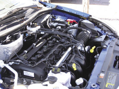
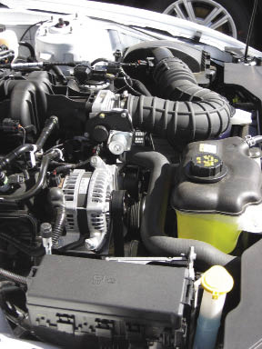
The images above and below are the engine compartments of 2010-model Ford vehicles. These shots
give an idea of the complexity and variety of underhood layouts. Ford’s new EcoBoost twin-turbo option (not
shown) takes up even more room beneath the hood.
Images courtesy of Chalmers Ford, Santa Fe, NM.
Immersive engineering and ergonomics in the virtual manufacturing toolset have also done away with the one-size-fits-all specifications for clearances. For decades, Ford used 3-in. clearances but everything changed in recent years. Under-the-hood space became precious as more components for electronic systems and emission controls plus cables, wiring, and tubing that must be fitted in.
The virtual manufacturing toolset revealed and verified that the old 3-in. hand clearance standard only applied to knuckles. “If the task is done with a finger-tip push, maybe we only need half a ½-in. clearance,” Stephens says.
“Conversely, we may actually need 5-in. of clearance if the assembler needs to use a tool.” To avoid collisions, the virtual manufacturing toolset has clearance checks coded in for all tool geometry. If a component violates them, the engineer is flagged.
A big boost in this regard, Stephens added, “is the infinite number of measurements we can take in the virtual manufacturing toolset. We can measure from any surface to any point. In the old days, we often had only one or two measurements to work with. If those were not what we needed, we had to extrapolate and that can lead to uncertainty.
Ford Motor Company
www.ford.com
Motion Analysis Corp.
www.motionanalysis.com
Siemens
www.siemens.com
Filed Under: Factory automation, Assembly, Automotive, ENGINEERING SOFTWARE, MECHANICAL POWER TRANSMISSION, Motion control • motor controls


Tell Us What You Think!