Careful design and selection of induction and permanent magnet ac electric motors will make them more energy efficient.
Gabriel Venzin • ABM Drives Inc. || ABM Greiffenberger U.S. Subsidiary
Efficiency in motor designs is a more relevant concern than ever. With electric motors providing over 60% of all industrial power, efficiency is a key design parameter. Here we’ll look at some general requirements as well as more specific ones for permanent magnet ac (PMAC) motors, which hold for common industrial applications in a limited power range.
To start, efficiency is defined as the ratio of delivered mechanical power to the supplied electrical power. An electrical motor that is 85-percent efficient converts 85 percent of electrical energy into mechanical energy. The remaining 15 percent dissipates as heat.
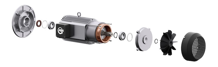
Exploded view rendering of an ac induction motor illustrating the housing, bearings and fan components.
Energy efficient electric motors use high-quality materials and optimized designs to achieve higher efficiencies. For example, more aluminum in the rotor and better slot-filling factor in the stator reduce resistance losses. Optimized rotor configuration and rotor-to-stator air gap reduce stray-load losses. Improved cooling fan design provides motor cooling with a minimum of windage loss. Higher quality and thinner steel laminations in the rotor and stator cores allow operation with substantially lower magnetization losses. Finally, reduced friction losses result from higher-quality bearings.
Selection points for both induction and PMAC motors
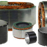
Optimizing the dimensions of rotor and stator laminations and the quality of steel used is key to improving performance: Hysteresis and eddy current losses together are called core losses. Around 20 percent of total losses are caused by eddy currents and magnetic core saturation.
Eddy currents induced in laminations moving relative to a changing magnetic field cause significant power losses. Laminated stator cores reduce eddy current losses and are based on the quality, resistivity, density, thickness, frequency and flux density of the iron. Eddy current losses can be minimized with a higher number of laminations.
Hysteresis losses are caused in the magnetic circuits when the flux is continually changing. The majority of flux-carrying material used in electric motors is steel used for stator and rotor cores.
Minimize the flux density and core losses by reducing the thickness of laminations. Hysteresis losses are reduced by annealing better grades of steel for laminations to change the grain structure for easy magnetization.
Reduce eddy current losses by increasing the resistivity of the steel with silicon, but silicon content increases die wear during stamping because it increases steel hardness. Steel crystals damaged during stamping severely degrade the magnetic quality of the affected volume.
Annealing flattens the laminations and recrystallizes the crystals damaged during stamping, which extends one sheet thickness into the lamination.
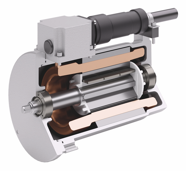
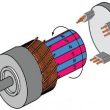
The special design of ABM’s Sinochron motor rotor with internal magnets leads to an almost ideal sine distribution of the magnetic flux. It’s designed for sensor-less control mode, making it an alternative to servo drives.
Use bath impregnation process for lamination, versus drip for optimum thermal management: Impregnating stators strengthens stator winding electrical insulation, protects against chemicals or harsh environments, and enhances thermal dissipation. Thermoset plastics including epoxies, phenolics, and polyesters are used for impregnating stators. ABM uses the bathing method whereby stators are immersed in resin for an extended period of time to assure optimum penetration and protection. Another impregnation method is called vacuum-pressure, which uses a tank that is evacuated first and then pressurized to achieve penetration into the stators. Driving out air pockets from the electric winding enhances the thermal conductivity of the winding.
Design slots in the stator to maximize the volume of copper that can be inserted: Low stator winding mass causes up to 60 percent of total losses, so to reduce them the mass of stator winding must be larger which reduces electrical resistance. Electric motors that are highly efficient contain more than 20-percent extra copper compared to standard efficiency electric motors. The stator’s insulated electrical windings are placed inside the slots of the steel laminations. The cross-sectional area must be large enough for the power rating of the motor.
In general, open or semi-closed stator slots are employed in induction motors. In semi-closed slots the slot opening is much smaller than the width of the slot, and winding is more difficult and time consuming to manufacture compared to open slots. However, the air gap characteristics are better compared to the open type.
The number of stator slots must be selected at the design stage because this number affects the weight, cost, and operating characteristics. The advantages of more slots are reduced leakage reactance, reduced tooth pulsation losses, and higher overload capacity. The disadvantages of more stator slots are increased cost, increased weight, increased magnetizing current, increased iron losses, poorer cooling, increased temperature rise, and reduction in efficiency.
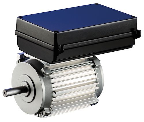
SINOCHRON PMAC motor efficiency is more than twice compared to standard asynchronous motors under partial-load. It’s made possible by a continuously excited synchronous motor, which operates with practically no rotor losses.
Use high grade or pure aluminum in the rotor die casting: Custom designed rotors can maximize starting torque, reduce conductor resistance and increase efficiency. Most induction motor rotors are squirrel-cage designs. They are rugged, simple in construction and less expensive, but they have a low starting torque. Copper rotors increase efficiency but are difficult and expensive to manufacture.
Tightening manufacturing tolerances allows optimum air gap between rotor and stator: The air gap is the radial distance between the rotor and stator in an electric motor for standard radial motors. An optimum air gap needs to be maintained for design efficiency. Air gap dimension involves the design of stator, rotor, motor housing, and bearings. All these affect the exact alignment of the stator and rotor axes.
Use copper windings that meet DIN EN 13601 and UL Norm standards: The European standard DIN EN 13601 specifies copper and copper alloys for general electrical purposes including dimensions and tolerances, tensile test, hardness test, bend test, electrical resistivity test. It also specifies characteristics of coppers for electrical purposes including the preference for oxygen-free or deoxidized coppers which may be heat-treated, welded or brazed without the need for special precautions to avoid hydrogen embrittlement which causes cracking.
For global compliance, UL determines that magnet wire complies with IEC 60317. Magnet or enameled wire is an electrolytically refined copper or aluminum wire that has been fully annealed and coated with one or more layers of insulation. ABM, for example, uses wires with a total of 12 insulation coats. Typical insulating films in order of increasing temperature range are polyvinyl, polyurethane, polyester, and polyimide up to 250 °C. Thicker rectangle or square magnet wire is wrapped with a high-temperature polyimide or fiberglass tape.
Use of more copper, larger conductor bars and conductors increases the cross-sectional area of stator and rotor windings. This lowers resistance of the windings and reduces losses due to current flow. A high-efficiency electric motor will usually have 20 percent more copper in the stator winding.
General electric-motor selection guidelines
The motor selection process involves some basic considerations. For starters, verify the application requirements. Then, what torque and speed is needed when and how often? What is the duty cycle? What are the ambient conditions such as temperature and pressure? Even the most efficient motor will not perform to its utmost efficiency if used for the wrong application.
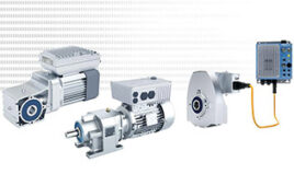
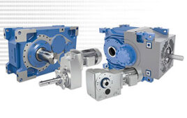
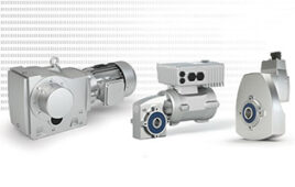
Many of the electric motors discussed here are used for gearmotors, a combination of a gear reducer and an electrical motor. A gearmotor delivers high torque at low speed. In short, gearmotors take motor power and reduce its speed while magnifying its torque.
Gearmotor duty cycles do not only impact the motor performance rating, e.g., a continuous duty cycle
S1 motor will provide a higher output if it’s used at an S3 intermittent duty cycle, but also especially for gearboxes used in extraordinary applications where torque peaks and system shocks are possible. For such situations, it’s critical to carefully determine what duty cycle and what peaks/shocks per a specific time period are experienced so the engineering team of the motor/gearbox OEM can select and recommend a suitable drive system.
A good start is to review data on past extreme temperature and or pressure conditions in which the application will be operating and any other unique conditions that may be relevant to the design. Always inform the motor OEM if your application is being used in extreme conditions – this can be a game changer.
Design motor housing for best cooling
The electrical efficiency of motors has improved so much that the power drawn by cooling fans has become a larger percentage of the total losses. Optimization of cooling fan dimensions involves using the minimum power for the fan, while providing adequate cooling. The optimal fan design may result in a 65 percent reduction in fan power requirements. An important design feature is the clearance between the blade and the housing. The space between the housing and the fan blade should be as small as possible to prevent turbulence and decrease backflow.
A cool motor runs more efficiently. To obtain the best airflow, optimize the cooling fan and fan shroud design. Assuring a tight bond between the stator and motor housing provides the best cooling performance.
Select low-friction bearings suited for operating speeds
Ball or roller bearings are used in high-efficiency electrical motors. They consist of an inner and outer race and cage containing steel or ceramic rollers or balls. The outer race is attached to the stator and the inner race to the rotor. When the shaft rotates, the element also rotates and the friction of the shaft rotation is minimized. They have a long life and maintenance costs are low. High precision application allows the smallest air gap possible. Thermal contraction and expansion can affect shaft and housing fits as well as internal bearing clearances.
Power output governs shaft size and bearing bore. Load magnitude and direction determines bearing size and type. Consider additional forces such as unsymmetrical air gaps causing magnetic pull, out-of- balance forces, pitch errors in gears, and thrust loads. For bearing-load calculations consider the shaft as a beam resting on rigid, moment-free supports. Ball bearings are more suitable for high-speed applications than roller bearings. High-speed factors include cage design, lubricant, running accuracy, clearance, resonance frequency, and balancing.
Knowing the ambient temperature range and the normal operating temperature range will help determine the most effective lubrication method for the bearing: oil or grease. Normal operating temperatures for gearmotors considered here range from -25 to 40 °C. Synthetic grease has good performance properties over a wide range of temperatures. Grease allows simplified maintenance, cleanliness, fewer leaks, and contaminant protection.
Bearings need a minimum load, so rolling elements rotate and form a lubricant film rather than skidding, which raises operating temperatures and degrades lubricants. Allow a minimum load equal to about 0.01 times the dynamic radial-load rating for ball bearings. It’s especially important when bearings are approaching 70 percent of recommended ratings.
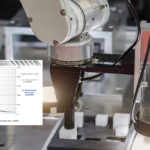
Use a quality balancing machine, high standards and balance at the operational speeds of the motor application: Noise and vibration can result when the center of mass does not co-exist with the axis of rotation. Balancing has limited effect on efficiency but impacts operating noise and life expectancy that is also important for maximum use of resources.
Bearing vibration readings are normally taken on three planes – vertical, horizontal and axial. Vertical vibration may indicate a mounting problem. Horizontal vibration may mean a balance problem, whereas axial vibration may indicate a bearing problem. Balancing at operational speeds is important because unbalance can also be caused by centripetal forces at the bearings.
Additional design criteria for PMAC motors
PMAC motors are a growing alternative to ac induction motors, which for decades have been the workhorse of almost any electrical motor application. PMAC motors preserve the reliability and simplicity of the ac induction motor while offering higher efficiency, synchronous operation, and the opportunity to use a smaller frame size.
PMAC motors replace the magnetic field induced in the conductors in the rotor with permanent magnets, usually made from alloys of rare-earth metals, giving them much lower electric resistive losses than ac induction motors because no electric current is induced in the rotor. In place of mechanical commutation, a control system is required to determine which coils are supplied with current to produce the maximum torque. Magnetic fields generated by rare-earth PMAC motors can deliver the same torque as ac induction motors with a smaller, lighter motor.
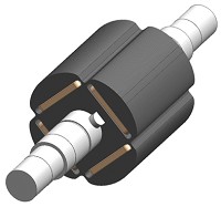
This illustration shows the special design of the SINOCHRON PMAC motor rotor laminations and the imbedded magnets that allow a sinusoidal motor motion.
Select PMAC motor size to allow operation in partial load area for best efficiency: Energy savings from PMAC motors depend on the number of service hours, motor size, and motor loading. PMAC motors nearly always maintain higher efficiency – no matter the speed or torque compared to ac induction motors and makes them an attractive alternative to induction motors in variable-speed applications. By substituting existing line-powered three-phase electric motors with PMAC motors, energy savings of 20 to 35 percent can be expected.
Optimize design of rotor laminations to show a sinusoidal magnetic field: For example, ABM synchronous motors with high-performance permanent magnets come with a sinusoidal flux distribution as well as Electro- Motive-Force. Stator windings, for distributed windings, are normally identical to asynchronous motor windings. It results in lowered vibration, noise and maintenance cost as well as increased overall performance.
Selection of rare earth versus ferrite (ceramic) magnets
Neodymium rare earth, samarium cobalt magnets or ferrite (ceramic) magnets are used in PMAC electric motors. Rare earth magnets are two to three times stronger than ferrite or ceramic permanent magnets but are more expensive. Samarium cobalt magnets are optimal for high-temperature applications because of their high energy density, 250 to 550 °C temperature resistance, small decrease of parameters due to temperature increase, and oxidation protection.
The selection of samarium cobalt or neodymium as an electric motor magnet is based on operating temperature, corrosion resistance and required performance. A low-grade neodymium magnet may begin to lose “strength” if heated above 80 °C. High-grade neodymium magnets operate at temperatures up to 220 °C.
Ferrite or ceramic magnets have won wide acceptance due to their strong resistance to demagnetization, exceptional corrosion resistance, and low price. Magnetic losses occur when operating at temperatures above 250 °C, but are recovered when the magnet is brought down to a lower temperature. Cold temperatures of -40 °C may result in permanent losses of magnetic strength unless the circuit has been designed for such extremes.
PMAC motors require inverters
PMAC inverter drive units can be loss-free in no-load operation/standstill. New motor design combinations offer advantages in powering conveying equipment, escalators, spooling machines, compressors and traction drive units. By substituting existing line-powered three-phase drive units, energy savings of up to 30 percent can be expected.
The characteristic profile of PMAC drive units makes them well suited to drive pumps and fans that operate continuously. No additional components, like encoders, are needed. Up to 25 percent smaller footprint allows machine designs to be more compact. The motors have excellent control behavior and combined with a sensorless drive controller unit, have excellent true running even at low speeds and impressive dynamics at impulse load and speed variations.
Select an inverter that can provide sensorless operation: Standard PMAC drives can “self-detect” and track the rotor’s permanent magnet position. This is critical for a smooth motor start and also allows for optimum torque production, which results in optimum efficiency. Lack of position or speed sensor reduces the cost and increases reliability of a drive system.
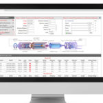
Programming and optimization of inverter: The importance of programming the controller settings for a specific motor to attain optimum efficiency is becoming more and more important with the ever- increasing efficiency regulations.
Choosing manufacturing partners: When choosing partners during a machine build, remember that there are two methods for choosing an electric motor source. Either pick a standard motor that might or might not fit a specific application or choose a competent motor partner to engineer and manufacture a motor that fits the application exactly.
Standard motor solutions are suitable if a design engineer doesn’t have the time or engineering resources to have a custom version engineered — or if it needs a quick setup. New modular approaches to design and construction let manufacturing engineers get reasonably priced custom motors even in modest volumes.
No matter the approach to motor selection, be sure to continually improve the design/drive system by comparing predictions of performance with measurements. Then use the result of the analysis to improve the next iteration.
ABM Drives • www.abm-drives.com
You may also like:

Filed Under: Gears • gearheads • speed reducers, Motors (gearmotors), Motion Control Tips
Tell Us What You Think!