Using one wire in two very different roles is widely done, requiring some simple circuity and basic components.
Using a headphone wire as an FM antenna
The earliest portable AM/FM portable radios used two antennas: an internal long wire wound on a ferrite core for the lower-frequency AM band (550-1600 kHz), and a “whip” antenna about one to two meters long for the FM band (88 to 108 MHz), (Figure 1).

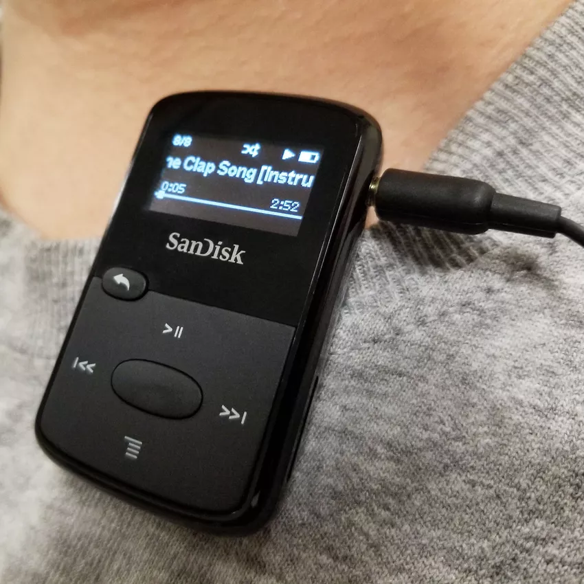
As these radios got smaller and even more portable, some eliminated their internal loudspeakers entirely and assumed their users would have headphones or wired earbuds instead. This enabled a simple technique for eliminating the FM whip via a simple re-purposing of the headphone jack connection within the radio. The same approach was then extended to MP3 players, which also included an FM-radio function (Figure 2). Many small electronic units still employ an FM-radio function, even as a peripheral function.
A basic headphone cable contains three conductors (Figure 3). The left and right audio channels are driven by a headphone amplifier onto the left and right audio conductors, while the common audio conductor is used for the audio return path. The same cable also functions as the FM antenna with an inductor to block RF from ground while allowing the audio signal to have a ground return. A small blocking capacitor allows antenna RF to pass to the receiver front end but blocks audio from that antenna input. The ferrite beads provide a low-impedance audio path and a high-impedance RF path between the headphone amplifier and the headphone.

Of course, an actual circuit is somewhat more complicated and requires some additional components for protection, voltage discharge, and assuring signals only go where they should (Figure 4).
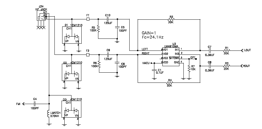
This design uses an LM4910 headphone power amplifier configured for that primary role along with the antenna-signal connection/separation circuit needed. The three-wire, left/right audio headphone jack receives the amplified audio signals from the LM4910 while the separated FM signal picked up by the headphone shield/ground is routed to the receiver front-end via a 100-pF capacitor.
It may seem that this technique should not be limited solely to FM-band broadcast signals. It is, and it isn’t: in theory, it could be used for any frequency as long as the headphone wire was the right length. The reason it works for the FM band is that a headphone cable with a length between about one and one-and-a-half meters is approximately half the wavelength of a broadcast-band FM signal (FM-band wavelength is about three meters), and so is resonant and effective in that band.
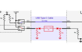
It is also possible to add an FM radio-antenna path to smartphones with USB Type-C Interface, using an IC such as the Maxim (now Analog Devices) MAX20328 MUX Switch for USB Type-C Audio Adapter Accessories. This IC, when properly managed, can provide the needed interconnection (Figure 5).
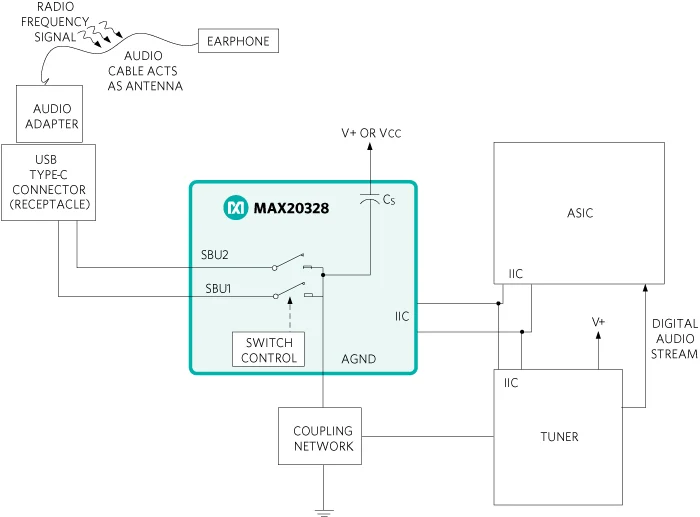
A full explanation of the operation of this topology and why it provides an FM antenna to a smartphone that has the processing power to decode the signal is provided in Maxim/ADI Application Note 6166, (see Reference). The lengthy note includes full design-in details, component-value analysis, and performance-test results.
There’s a somewhat ironic update to the use of the headphone cable as an FM-band antenna: the popularity of wireless earbuds with smartphones and other personal portable devices has rendered this simple solution to the antenna problem no longer be an option.
Conclusion
Engineers have always sought to leverage an available resource such as a cable for multiple uses. With the simple addition of some inductors, capacitors, and resistors, it is feasible to have DC power, RF signals, and audio signals share the same cable (but only two of the three on any single wire). These configurations are low cost, reliable, and do not have the complexity of software, configuration, set-up, handshaking, or other challenges of more advanced “sharing” systems such as USB-based power, powerline for Internet, or Power over Ethernet schemes.
Related EE Word Content
- Triple-band GNSS low-profile helical antenna features small form factor
- Surface-mount antennas cover GPS high-precision, correction bands
- DLNA Approves HomePlug AV and HD-PLC Powerline Networking for Increased Digital Home Connectivity
- The complexity of wireless receiver testing
- Gadgets: Several Decisions To Be Made Before Selecting New Headphones
- Microphone Product Family Adds Calibrated System With Phantom-Powered Preamplifier
External References
- ProSoundWeb, “A Primer On Phantom Power For Condenser Microphones”
- SweetWater, “What is Phantom Power and why do I need it?
- Electrical Engineering,” Can anyone explain Phantom Power and, specifically, how it’s used in satellite television systems?”
- Elliott Sound Products, “48V Phantom Feed Supply for Microphones”
- Instructables, “Make a Mobile Antenna to Listen to FM Radio Without Headphones”
- Learning Electronics, “Antenna Input & Audio Lineout Adaptor For Portable Radios”
- Skyworks Solutions, AN383, “Si47xx Antenna Schematic, Layout, and Design Guidelines”
- NXP Semiconductor, AN11420, “NXP GPS LNA – GPS LNA voltage supply via a coax cable
coming from the GPS receiver” - Maxim/Analog Devices, Application Note 6166, “MAX20328 Adds FM Radio Antenna Path to Smartphones with USB Type-C Interface”
You may also like:
Filed Under: Connector Tips