Design World

  • Home
  • Articles
    • 3D CAD
    • Electronics • electrical
    • Fastening & Joining
    • Factory automation
    • Linear Motion
    • Motion Control
    • Test & Measurement
    • Sensors
  • 3D CAD Models
    • PARTsolutions
    • TraceParts
  • Leadership
    • 2020 Winners
    • 2019 Winners
    • LEAP Awards
  • Resources
    • Subscribe
    • DIGITAL ISSUES
      • EE World Digital Issues
    • Future of Design Engineering
    • LEAP Awards
    • MC² Motion Control Classroom
    • Motion Design Guide Library
    • Podcasts
    • Suppliers
    • Webinars
  • Women in Engineering
  • Ebooks / Tech Tips
  • Videos
  • COVID-19

Helical Gears Versus Traditional Worm and Spur Gears

By Laura Carrabine | April 6, 2011

Share

Gears have evolved over the last decade. Worm gears have sliding surfaces but thay can have higher friction. Spur gears have rolling surfaces, but because the teeth are cut straight across on a face; one or two teeth at a time are in contact with another gear, which can create high noise. Worm and spur gears are less expensive to manufacture, but they typically last about three years before they need to be replaced.
worm-gears

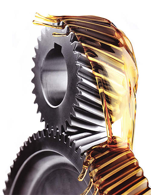
Worm gears typically require lubrication and may have shorter life cycles than helical gears, depending on the application.

“Another option is to use high-quality gear reducers,” said Bernd Stober, owner and former helical gearing designer at STOBER Drives. “Gear reducers typically run cool and quiet for many years.”

Helical gearing is machined to have angled teeth, then hardened and ground to achieve an efficient gear mesh. The teeth angle enables the gears to gradually mesh. Thus, two or three teeth of each gear are always in contact with other gears. This configuration lessens the load on each tooth and creates a smooth transition of forces from one tooth to the next. The result: less vibration, wear, noise, and a longer life.

Helical gear reducers come in many shapes, sizes, and configurations, helping you eliminate high wear and high maintenance parts such as belts, pulleys, chains, and sprockets.

There are two common quality indicators in gearing—high noise and vibration—which result in low precision and limited life.

Rotating machines that generate high noise and high vibration can have any number of quality issues. Rotating components may not be balanced properly, which causes vibration. Mating components may be machined to tolerances that are not precise regarding perpendicularity, concentricity, and true position. Or, components may not be rigid enough, flexing under load, which can result in misalignment.
Stober-helical-gear-reducers

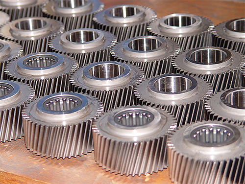
Stober helical gear reducers come in many shapes, sizes, and configurations.

The noise level of helical gearing is approximately 10-12 dB (A) lower than spur gearing. That means 16 helical gear units generate as much noise as a single spur gear unit. An additional benefit is that silent gears are better for employee hearing.

Another issue is high heat generation, which indicates low efficiency and wasted energy. High heat generation is the result of low efficiency in rotating machines, which can also have many causes including inefficient design, misalignment, incorrect fits, and large seal diameters creating drag.

Helical gearing is 20% to 30% more efficient than single stage worm gearing. With a 2 hp motor, up to 4,000 kWh energy can be saved per year. Also, you can opt for a smaller motor because the losses in the gear reducer are lower.

STOBER Drives
www.stober.com

Tell Us What You Think! Cancel reply

MOTION DESIGN GUIDES

“motion

“motion

“motion

“motion

“motion

“motion

“motion

“motion

“motion

Enews Sign Up

Motion Control Classroom

Design World Digital Edition

cover

Browse the most current issue of Design World and back issues in an easy to use high quality format. Clip, share and download with the leading design engineering magazine today.

EDABoard the Forum for Electronics

Top global problem solving EE forum covering Microcontrollers, DSP, Networking, Analog and Digital Design, RF, Power Electronics, PCB Routing and much more

EDABoard: Forum for electronics

Sponsored Content

  • Drilling rig OEM benefits from a PLC with edge computing technology: IIoT case study
  • The industry shift to smart electromechanical actuators
  • Commemorating a great entrepreneurial personality – Oskar Lapp at 100 – A pioneer for the future
  • SE motor – uncompromised motion performance
  • With virtual commissioning, commissioning time and prototype waste is reduced
  • Master Bond Supreme 10HT High strength, NASA low outgassing approved epoxy
Engineering Exchange

The Engineering Exchange is a global educational networking community for engineers.

Connect, share, and learn today »

Tweets by @DesignWorld
Design World
  • Advertising
  • About us
  • Contact
  • Manage your Design World Subscription
  • Subscribe
  • Design World Digital Network
  • Engineering White Papers
  • LEAP AWARDS

Copyright © 2021 WTWH Media, LLC. All Rights Reserved. The material on this site may not be reproduced, distributed, transmitted, cached or otherwise used, except with the prior written permission of WTWH Media. Site Map | Privacy Policy | RSS

Search Design World

  • Home
  • Articles
    • 3D CAD
    • Electronics • electrical
    • Fastening & Joining
    • Factory automation
    • Linear Motion
    • Motion Control
    • Test & Measurement
    • Sensors
  • 3D CAD Models
    • PARTsolutions
    • TraceParts
  • Leadership
    • 2020 Winners
    • 2019 Winners
    • LEAP Awards
  • Resources
    • Subscribe
    • DIGITAL ISSUES
      • EE World Digital Issues
    • Future of Design Engineering
    • LEAP Awards
    • MC² Motion Control Classroom
    • Motion Design Guide Library
    • Podcasts
    • Suppliers
    • Webinars
  • Women in Engineering
  • Ebooks / Tech Tips
  • Videos
  • COVID-19