Proper design of motor control systems for engines make it possible to maximize the engine’s efficiency during the design phase. Understanding the control needs of each type of engine, and the most appropriate style for a given application, can help to ensure greater efficiency in any context.
A direct current motor belongs to a class of electric machines that converts direct current electricity into a mechanical one. The most common types base their functioning on the classical laws deriving from magnetic fields. Almost all types of DC motors have some internal mechanism, electromechanical or electronic, which allows to periodically change the direction of the motor current flow (Figure 1).
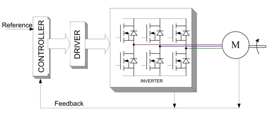
Figure 1: Block diagram of a DC motor.
The engine in constant current brushes is most frequently used, even considering the type of emerging applications, but the number of brushless motors in constant current brushless DC electric motors is constantly growing. The third type of engine is the step-by-step that is strictly connected to the BLDC, but whose use is limited to applications with specific needs (e.g. servosystems). Probably the most widespread type of motor is the induction AC motor in c.a., while the synchronous motor with permanent magnets or permanent magnetic synchronous motors (PMSM) could be its possible substitute. Efficiency in the AC induction motor in c.a. is closely related to power factor correction that can significantly improve typical application performance, including HVAC systems, home appliances, and industrial applications.
In fixed-speed applications, controlling an AC induction motor is relatively simple; the speed is directly connected to the frequency of the control voltage. On the other hand, a PMSM is more suitable for variable speed or torque applications, but is more complicated to control, although it is more efficient than an AC induction motor.
Motor Drivers
The transition to Industry 4.0 has accelerated the adoption of robots, cobots, and other advanced machines in the factory to generate even higher levels of productivity. However, with this, new design challenges arise in the control of precision movement, communication interoperability and determinism, and increased use of sensors for location detection and security.
In the case of a brushless DC motor engine, the drive is very complicated. Transients are used instead of brushes, while the speed and torque are controlled by the on/off/duration ratio of the transients. Usually the whole takes the form of a signal Pulse Width Modulation (PWM) used to operate the windings. This condition is further complicated by the use of single-phase, two-phase, and three-phase motors, which transmit a progressively more regular rotation movement by increasing the number of phases (and, consequently, of PWM signals) in each case.
Today, many integrated devices offer the drive stage for several engines, including BLDC, PMSM, and step-by-step. They usually include the gate drivers needed to drive external power MOSFETs used to excite up to three engine phases. One example is the STK5C4U332J-E device from ON Semiconductor, an intelligent power module for driving three-phase motors, suitable for PMSM, BLDC, and AC synchronous motors (Figure 2).
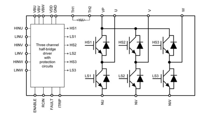
Figure 2: Block diagram of ON Semiconductor’s STK5C4U332J-E.
Microchip offers a complete line of three-phase, single-chip, brushless drivers and three-phase MOSFET gate drivers for brushless motors for a wide range of motor applications. These products are designed to interface with any microcontroller or be used in an autonomous configuration.
For single-chip drivers for BLDC motor control, the MTD6501 is suitable for many solutions. For MOSFET gate drivers for BLDC motor control, the other solution is the MCP8024. Microchip’s 8-bit PIC MCUs are an excellent solution for simple sensorless or sensorless trapezoidal control (Figure 3).
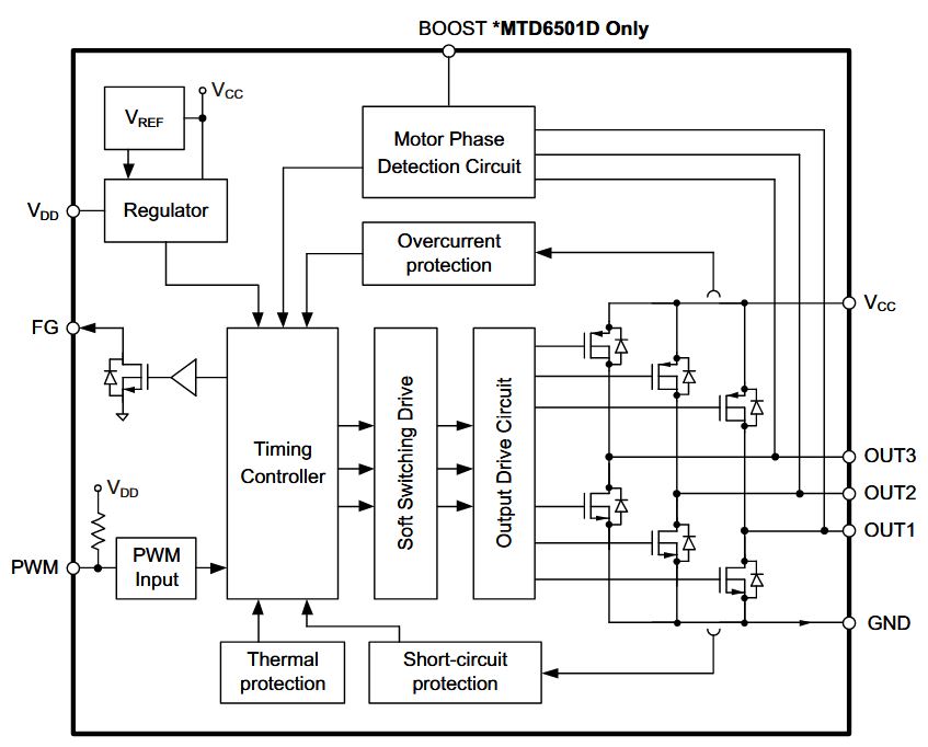
Figure 3: Block diagram of Microchip’s MTD6501.
Optical Coupling
One of the most expensive devices in a motor control system is a power semiconductor switching device, such as an IGBT or power MOSFET. By switching at high frequency, these power devices introduce unexpected noise and high voltage transients through the control system. The high-frequency transient can affect the normal operation of the sensitive and expensive microcontroller. Sigma-Delta modulators, in combination with the superior optical joint isolation technology, offer high noise margins and high immunity against isolation mode transients. With a minimum distance through the insulation (DTI) of 0.5 mm, these sigma-delta modulators provide reliable double protection and a high working voltage suitable for safe projects. This proven insulation performance is superior to magnetic or capacitive insulators, where DTI is only a third of 0.1 mm.
Isolated sigma-delta modulators ACPL-796J and ACLP-C799 from Broadcom (Figure 4) are two types of sigma-delta modulators, based on the fact that the clock source is internally incorporated or supplied externally to the modulator. For the internal clocked type, a 10 MHz clock is integrated into the primary side of the isolation barrier in which the sigma-delta encoder is located. The clock signal is encoded together with the data and coupled through the isolation barrier to the secondary side of the isolation barrier where the clock and data signals are decoded.
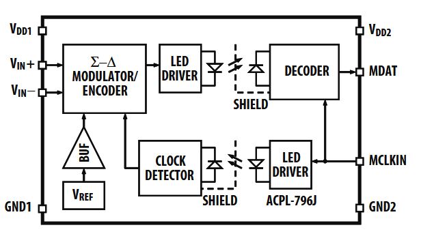
Figure 4: Block diagram of Broadcom’s ACPL-796J.
Stepper Motors
Reducing energy consumption is essential and is a goal to be pursued by working on every aspect of production. In this, the automation comes to help with more efficient devices, modules for braking energy recovery, intelligent software for process optimisation, etc.
Every device, even the smallest, contributes to efficiency. For instance, the stepper motor control module of the B&R X20 family, with an integrated current reduction function, not only guarantees better control performance, but also allows vital energy savings.
B&R’s X20 SM1436-1 module can be used for stepper motors with a voltage from 18 to 60 VDC with currents up to 2.5 A. The integrated current reduction function increases performance and reduces energy consumption. With this function, in fact, B&R has integrated a current control without hints, depending on the load, which significantly increases the performance of the module. By adjusting the current according to operating conditions and load, the module allows for savings of up to 75 percent.
The current reduction function significantly reduces power dissipation and heat build-up in the module. At the same time, current control also has an impact on the stepper motor that works more smoothly. For self-protection, the module has an input current limiter and an output with short circuit and overload protection.
Filed Under: Appliance engineering + home automation, Product design, Motors • stepper