By Mike Santora
The “u” in U-joint could just as easily stand for ubiquitous or unchanged. But unique? Hardly. For almost a century, universal joints have been created with the same fundamental design. Sure, they’ve been improved since their first incarnations; they’ve gained needle bearings, increased machining qualities, and lubrication and sealing abilities. Regardless, the basics haven’t changed in a while. Now, a new basic design is in the works to bring smoother, more efficient motion to the old component.
Perlberg and Sweetwood say that they have been able to maintain a good, consistent fit between the central element and the yokes for a smooth sliding, strong torque transferring unit.
When a major forklift manufacturer came to CCTY Bearing to ask for help with a U-joint problem, CCTY’s Head of Engineering for North America, Rich Perlberg and Strategic Sales Manager John Sweetwood had their work cut out for them. The forklift manufacturer was seeing repeated failures in its steering linkages and the space envelope was too small to go up in size.
“It was the kind of space envelope issue where they needed a larger load capacity but didn’t have more room to pack anything in there. Rich started working on the project and a few months later he got me involved with it,” said Sweetwood.
It was during the U-joint section of a design software training course that led Sweetwood and Perlberg to the Square Ball U-joint’s eureka moment.
“By the fourth day of class we were done designing some of the fundamental components. Then it was time to do an assembly. The project was on a U-joint. I was looking at the assembly and simulating the movement with it. I noticed that when I broke down the movement to just one yoke it rotated on one axis, the other one opposite would rotate on an axis 90° to it. It was the combination of those two motions. When you’re rotating through it, you have the same motion you would have with a U-joint. I hit Rich in the arm and said, ‘Rich, we need a square ball,’” said Sweetwood.
The term “square ball” didn’t conjure images of smooth, elegant motion and it wasn’t particularly clear what it would even look like. It was up to Perlberg to go home that night and try to draw the new component into existence.
“The next day he came into class and showed me his drawing. I said, ‘Yes, that’s what I was trying to tell you,’” said Sweetwood.
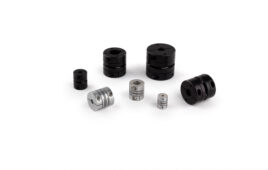
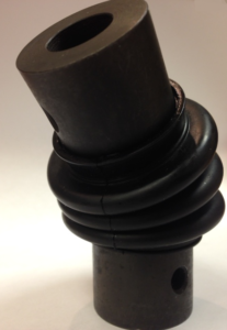
It’s a lean and simple construction. Six parts total: two yokes, one central element (the square ball), two retaining pins and the seal to protect the moving parts and hold the grease in. The design functions much like a spherical plain bearing; the advantage being spherical plain bearings have a large load zone and the contact area is spread out over a large surface.
This design element allows pounds per square inch to remain low on the material compared with the needle bearings typically found in a universal joint. The load zone is basically the line contact the designer is getting with each needle bearing in the load zone. The square ball U-joint spreads that out and can handle the loads quite efficiently.
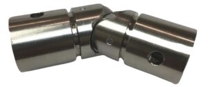
Perlberg and Sweetwood say that they have been able to maintain a good, consistent fit between the central element and the yokes for a smooth sliding, strong torque transferring unit. And while the above video makes the U-joint’s motion more clear, the company still receives questions.
Six parts total: two yokes, one central element (the square ball), two retaining pins and the seal to protect the moving parts and hold the grease in. The design functions much like a spherical plain bearing; the advantage being spherical plain bearings have a large load zone and the contact area is spread out over a large surface. This design element allows pounds per square inch to remain low on the material compared with the needle bearings typically found in a universal joint.
“I’ve actually had a number of engineers ask if the pins are needed to help transfer the torque. The answer is that they really don’t. They’re in the center of the whole yoke and the center of the ball. All the torque is transferred out towards the outer corners of the ball off the outer edges of the yoke. The pin is only there to keep the ball from sliding out either end. When it’s traveling or rotating at a high enough speed—and everything’s perfect on the loading—the pins don’t even need to be there,” said Sweetwood.
Perlberg and Sweetwood experimented and found that once the ball started rolling, it stayed centered. The ball seeks its own center and finds it. It still transfers the torque without it, but the pins are only there to keep the central element into the yokes together where it just keeps it from sliding out the side cylinder.
Even though the design has progressed consistently since its inception, it has not been completely without it’s challenges. There are still elements to improve upon.
For example, Perlberg and Sweetwood made it clear they didn’t want to imply that the current design has a high rotational torque. It is actually quite low. Additionally, this design in not yet suited for constant duty applications.
Down the line, CCTY sees potential for this component being modified into a constant velocity joint. “There are some ways we might be able to adapt this into a constant velocity joint. With how well it transfers torque in a small package, a constant duty application would be the next challenge. We still have a little ways to go,” said Sweetwood.
For now at least, CCTY’s focus is bringing the U-joint design to market.
CCTY received the provisional patent early this year and has added some additions to the U-joint since then. Sweetwood and Perlberg say they are doing a variety of tests right now from life testing to destruction testing.
“We’re at the point where we’re pretty close to nailing down what standard size would best serve the markets that we studied. Then we can figure out what our production costs are going to be and what tooling we’re going to need to bring this to market,” said Sweetwood.
CCTY has visited numerous customers with the new component and have created 3D printed models to help customers understand what a “square ball” is. Sweetwood said simply, “It’s kind of one of those things that really doesn’t exist by definition, I suppose, but it’s the closest two words to actually describe it.”
As for an estimated product launch, CCTY is hoping for a late Spring 2017 release. Perlberg is optimistic.
“Our typical lead time from the point we get a purchase order to being able to deliver product is about four months. Assuming testing goes well I’d like to think that a user will have this ready for their design, by next summer or late spring. That would be great.”
CCTY Bearing
www.cctybearing.com
Filed Under: Coupling Tips