Design World

  • Home
  • Technologies
    • 3D CAD
    • Electronics • electrical
    • Fastening & Joining
    • Factory automation
    • Linear Motion
    • Motion Control
    • Test & Measurement
    • Sensors
    • Fluid power
  • Learn
    • Ebooks / Tech Tips
    • Engineering Week
    • Future of Design Engineering
    • MC² Motion Control Classrooms
    • Podcasts
    • Videos
    • Webinars
  • LEAP AWARDS
  • Leadership
    • 2022 Voting
    • 2021 Winners
  • Design Guide Library
  • Resources
    • 3D Cad Models
      • PARTsolutions
      • TraceParts
    • Digital Issues
      • Design World
      • EE World
    • Women in Engineering
  • Supplier Listings

Hollow-bore Servo Motors

By Miles Budimir | June 18, 2013

Share

Servo motors come in many shapes and sizes, from small horsepower hobby motors to larger horsepower industrial motors. Most servo motors have the look and operation of a classical motor; that is, stator, rotor, and an output shaft which is connected to some other component to transmit motion. But not all applications have a need for an output shaft; in other words, in some applications, the shaft only gets in the way. 

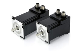
A special class of servo motors are ones with hollow shafts, also known as hollow bore motors. The defining characteristic of such motors is the hollow space through the center portion of the motor which makes it possible to pass various supplies through the center such as power cables, piping or hoses. In many cases, this simplifies the design of many systems including industrial robots and other machinery.

One company with a broad hollow bore motor line is Stober Drives, with offices in Maysville, Ky.

Last fall, the company released a new line of hollow bore servo motors called the EZF/PY into its existing line of hollow-bore motors. This line of motors uses an orthocyclic linear winding process making it possible to manufacture stator windings with a high copper fill factor. The winding technology increases the motor power output by approximately 80%, making it possible to shorten the length of the motor by almost half without reducing power output.

According to Dean Malott an electrical engineer with Stober Drives, one of the chief differences between Stober’s through bore motors and other motors is the fact that the hole goes all the way through the motor, as opposed to other designs which feature blind holes and don’t go all the way through.

Another feature of the motors is that they are self-contained units ready to mount, which means they don’t require any additional hardware for mounting to machines. They also incorporate an encoder mounted on the motor housing.

Another motor series, the EZM/EZS, is designed to work with ball screw applications. These motors use the same motor technology but use heavier bearings designed to hold up to the axial and radial loads inherent in these types of applications. The motors can be used to move along with the ball nut or as a spindle motor to turn the ball screw.

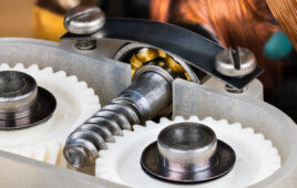
Because of the small size and hollow bore this can allow OEM’s to save space and make a cleaner design with these type of applications without belts and pulleys, or chains and sprockets that would traditionally be used.

Motion Control Tips


Filed Under: Motion Control Tips
Tagged With: STOBER
 

Related Articles Read More >

New gearboxes for electric motors in mobile machines
Leading motion-control and actuation options for robotics
Basics of wave and cycloidal gearing for robotics and servo designs
New micro servo-drive system for extra-low-voltage manufacturing applications

DESIGN GUIDE LIBRARY

“motion

Enews Sign Up

Motion Control Classroom

Design World Digital Edition

cover

Browse the most current issue of Design World and back issues in an easy to use high quality format. Clip, share and download with the leading design engineering magazine today.

EDABoard the Forum for Electronics

Top global problem solving EE forum covering Microcontrollers, DSP, Networking, Analog and Digital Design, RF, Power Electronics, PCB Routing and much more

EDABoard: Forum for electronics

Sponsored Content

  • Pushing performance: Adding functionality to terminal blocks
  • Get to Know Würth Industrial Division
  • Renishaw next-generation FORTiS™ enclosed linear encoders offer enhanced metrology and reliability for machine tools
  • WAGO’s smartDESIGNER Online Provides Seamless Progression for Projects
  • Epoxy Certified for UL 1203 Standard
  • The Importance of Industrial Cable Resistance to Chemicals and Oils

Design World Podcasts

June 12, 2022
How to avoid over engineering a part
See More >
Engineering Exchange

The Engineering Exchange is a global educational networking community for engineers.

Connect, share, and learn today »

Design World
  • Advertising
  • About us
  • Contact
  • Manage your Design World Subscription
  • Subscribe
  • Design World Digital Network
  • Engineering White Papers
  • LEAP AWARDS

Copyright © 2022 WTWH Media LLC. All Rights Reserved. The material on this site may not be reproduced, distributed, transmitted, cached or otherwise used, except with the prior written permission of WTWH Media
Privacy Policy | Advertising | About Us

Search Design World

  • Home
  • Technologies
    • 3D CAD
    • Electronics • electrical
    • Fastening & Joining
    • Factory automation
    • Linear Motion
    • Motion Control
    • Test & Measurement
    • Sensors
    • Fluid power
  • Learn
    • Ebooks / Tech Tips
    • Engineering Week
    • Future of Design Engineering
    • MC² Motion Control Classrooms
    • Podcasts
    • Videos
    • Webinars
  • LEAP AWARDS
  • Leadership
    • 2022 Voting
    • 2021 Winners
  • Design Guide Library
  • Resources
    • 3D Cad Models
      • PARTsolutions
      • TraceParts
    • Digital Issues
      • Design World
      • EE World
    • Women in Engineering
  • Supplier Listings