Calculations of ball screw service life and permissible static load take into account loads and forces that are predictable and quantifiable — thrust loads due to acceleration, process forces, and forces generated when holding a load in place, for example. But some applications are also susceptible to loads caused by shock and vibration — loads that are difficult to predict and quantify.
Shock and vibration loads can occur during standstill (static loads) or when the machine is moving (dynamic loads). In ball screw applications, shock, or impact, is often caused by sudden deceleration and hard stops, such as when a machine jams (preventing the screw from moving despite the motor applying torque) or when a pressing application doesn’t allow sufficient deceleration time at the end of the stroke.

Brinelling is often caused by shock or impact loads that exceed the static load capacity of the ball nut.
Image credit: Schaeffler
Vibrations are inherent in machine tool applications, where cutting or grinding operations induce vibrations in the tool, which “feeds” those forces back into the screw. Regardless of the cause, the consequence of vibratory loads is typically false brinelling, whereas severe static overload (shock or impact load) often results in true brinelling.
Both conditions produce regularly spaced indentions in the raceway of the screw shaft and can result in premature fatigue failure of the screw. Screws that experience vibrations when not moving are at an even greater risk of false brinelling, because when the screw and nut aren’t moving, there is no lubrication layer to help protect against damage to the raceway. This is why screw manufacturers often recommend shorter, more frequent lubrication intervals for ball screws that are subjected to vibration loads.
When calculating the L10 life of a ball screw, some manufacturers recommend multiplying the applied axial load by a “load factor” ranging from around 1.2 for applications with low shock and vibration forces, to 3.5 or 4 for applications with the potential for high shock loads and vibrations.

L = rated life of ball screw (rev)
C = dynamic load capacity (N)
F = applied axial load (N)
fw = dynamic load factor
Similarly, when comparing the applied static load to the static load capacity of the screw, manufacturers recommend that the applied static load be multiplied by a load factor ranging from 2, for low vibration and shock loads, up to 7 for machine tool applications that can encounter significant vibration or shock loads.

F0max = maximum permissible static load (N)
C0 = rated static load capacity (N)
S0 = static load factor
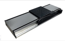
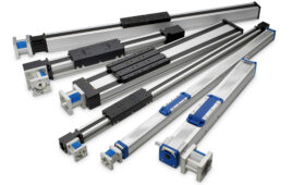
Loads due to shocks and vibrations can occur in both the axial and radial directions, but ball screws are designed to withstand only axial loads. This is why most ball screw applications incorporate linear guides — to support any radial loads that the system experiences. When sizing linear guides to be used in conjunction with a ball screw drive, it’s important to consider the potential for these additional loads due to shock and vibration.

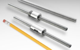
Planetary roller screws are capable of withstanding higher loads because the rollers provide more contact points.
Image credit: Tolomatic
For applications that experience very high shock and vibration loads, planetary roller screws can provide better performance and longer life than ball screws. This is because planetary roller screws have significantly more contact points — with rollers carrying the load — so they can withstand higher dynamic and static loads.
Feature image credit: Thomson Linear
Filed Under: Linear Motion Tips