High-precision test, measurement, and manufacturing operations often require smooth, frictionless, low-maintenance motion control systems. An excellent choice for a complete motion subsytem is a linear or rotary stage that uses an air bearing for guidance, coupled to a direct-drive motor, a high-resolution position encoder, and a digital controller.
Air bearings support a load with a thin film of pressurized air between the fixed and moving elements. They are typically referred to as aerostatic bearings, because a source of pressure rather than relative motion supplies the film of air.

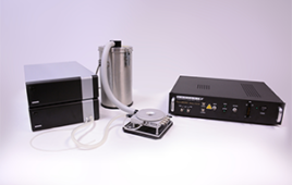
The Aerotech ABL1500 uses an air-on-air preload and a direct drive slotless ironless linear motor to provide 200-nm accuracy.
Unlike ordinary bearings, the surfaces of an air bearing do not make mechanical contact, so these systems do not need to be lubricated. Because the surfaces do not wear, the systems do not generate particulates, which makes them suitable for clean-room applications. When supplied with clean, filtered air, the bearings can operate without a failure for many years.
Friction is extremely low, generated only by the viscous shearing of the air film between the surfaces. In most cases (with surface speeds of 5 m/s or less) the friction force can be assumed to be zero. Rotational travel is unlimited while linear travel is limited only by the length of the component. Air bearing stages with travel longer than 1 m are commonly used in making flat panel displays. Bearing loads are generally distributed over a large area, so they can be quite high (more than 100 kg) but the maximum payload is proportional to the size of the bearing.

The ABL9000 shows a cable management system with examples of vacuum, magnetic, and air-on-air preloading.
All aerostatic bearing systems share the same common elements but differ in their detailed implementation. For example, although all air bearing surfaces contain a flow-restricting element of some sort; it can be an orifice, a slot, or a porous pad. Here, the high-pressure air flows through the gap (generally on the order of microns) and exhausts at atmospheric pressure.
The load-carrying capacity of the bearing is determined by the integral of this pressure distribution over the bearing area, and the stiffness of the bearing is estimated as half the load capacity divided by the gap. Smaller gaps are generally preferred because they increase the stiffness and reduce the flow, but manufacturing tolerances and thermal expansion allowances limit just how small the gap can be. The ABL1500 uses an air-on-air preload and a direct drive, slotless ironless linear motor to provide 200-nm accuracy.

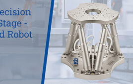
This is a large format ABL9000 with travel of 1 m by 1 m.
Typical air bearing system stiffness values are a few hundred N/µm which can approach the stiffness of the components used in the stage construction itself. The stiffness of air bearings is nonlinear over longer displacements, and the effective stiffness usually increases with preloads. Common methods for preloading include gravity, opposed pads (in which one air bearing element pushes against another), magnetic attraction, and vacuum pads. Usually the details of the overall mechanical design and the preloading method in particular, determine the overall geometric performance of the air bearing system more than the individual elements. A look at components
Most air bearings are purchased as complete electromechanical systems. An air bearing stage system includes the bearings, a drive motor, a position sensor, and a control system.
The preferred motor is usually a direct-drive type, and slotless ironless motors are preferred over iron-core motors. Slotted motors can generate higher forces, but the “cogging force” inherent in this design generates unwanted error motions directly proportional to the air bearing stiffness.
Previously, ball screws drove many linear air bearings and the challenge was to design a stiff, but non-influencing coupling between the screw and the carriage. Noncontact linear motors have eliminated this problem and replaced ball screw drives in all but unique applications.
The position sensor used with air bearings is usually a high-resolution, noncontact encoder. High-resolution is important because of the air bearing’s extremely low inherent damping. Damping in the servo dynamics must come from servo control, and an accurate estimate of velocity is critical. In general, however, the drive and control requirements for an air bearing stage system are no different than for any high-precision motion control system. Air bearing advantages
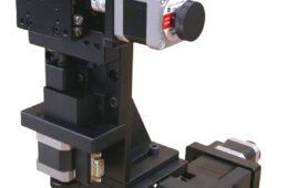
Air bearing systems offer many advantages that lead to their widespread use. For example, geometric error motions are usually at micron to submicron levels. In linear stage terminology, these are the straightness and flatness errors. In rotary stages, these are the radial and axial error motions. The ABRS series of rotary air bearing stage has an integrated motor and noncontact rotary encoder, uses magnetic preloading, and provides radial and axial error motions of less than 250 nm and 100 nm, respectively.
What is more important is that the errors usually repeat, at levels in the tens to hundreds of nanometers. The frictionless guidance, or lack of “bearing rumble,” also contributes to extremely constant-velocity motion.

The ABRS series of rotary air bearing stage has an integrated motor and noncontact rotary encoder, uses magnetic preloading, and provides radial and axial error motions of less than 250 nm and 100 nm, respectively.
Air bearing stages do not generate particulates, which makes them well suited for cleanroom applications. Because the air flows out of the bearing gap, small particulates are generally flushed from the bearing gap, making them self-cleaning (at least for small particles).
The lack of any mechanical contact also means that the stage does not wear, so it is essentially maintenance-free. Finally, for systems that require extremely high in-position stability, the airflow can be stopped in a coordinated shutdown with the servo to lock the stage carriage to the base. Air bearing limitations
Air bearing stages have a few limitations. A source of clean, dry air is necessary for operation. The small gaps and flow passages require the air to be filtered to submicron levels and dried to prevent condensation. The air in the gap expands and cools as it goes from high-pressure to atmospheric pressure, and any moisture present can condense on the air bearing surfaces. Nitrogen is often used, when available, for a stable, dry, clean air supply.
Designers must also take precautions to ensure that a system is not damaged from loss of the air supply. A pressure switch usually commands the controller to stop stage motion. In some cases an accumulator tank can supply air long enough to stop this motion.
In general, since load-bearing capacity is proportional to area, air-bearing stages are somewhat larger than equivalent stages using rolling-element bearings. Finally, air-bearing stages are not particularly suitable for vacuum environments. The ABL9000 shows a cable management system with examples of vacuum, magnetic, and air-on-air preloading.
Installation tips when using air bearings
You can take several steps to make the most of the benefits of an air bearing system. The first step is to maintain the supply of clean, dry air. It is also critical that the air bearing be mounted to an extremely flat base. The air bearing gaps are measured in microns, and mounting surfaces that are not flat will distort this gap. Rough surfaces generate geometric errors, and in the worst case damaging mechanical contact.
Ideally, air bearings should be mounted on granite bases. The granite can be readily lapped to a recommended flatness of 1 um per 50 mm and is very stable over time. The same tolerance holds when mounting accessories to the stage carriage. Three-point or kinematic mountings can be designed that work very well. Large format ABL9000 with travel of 1 m by 1 m. Cables are usually the biggest source of disturbance forces on air bearing stages. Stage manufacturers generally use high-flex cable for motor drive and encoder feedback, and can include extra conductors for customer use when discussed early in the design process.
Finally, you should view an “air-bearing” as only one part of a complete electromechanical motion control system. The motor’s smoothness, position feedback accuracy, mechanical design, cable management, and feedback control algorithms are all as important to the overall system performance as are the specific details of the bearing technology.
Stephen Ludwick is the Director of Advanced Technology at Aerotech Inc. ⚙️ Article updated November 2019.
You may also like:


Filed Under: Stages • gantries, Motion control • motor controls

Tell Us What You Think!