Need some tips for selecting the optimum motor and drive combination for your latest high-speed spindle application? Read on to find out why this oft-misunderstood process is far simpler than you think.
You will have almost certainly noticed that more and more high-speed electro-spindles on modern machine tools are built using permanent magnet synchronous motors. Why? They not only help to reduce the machine footprint, but improve surface finish accuracy and quality as well.
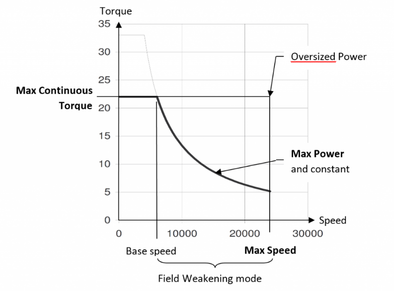
In the first instance, the application must be studied in continuous mode, and the design engineer has to define the desired maximum speed, along with the maximum continuous torque to be applied for low-speed deep-cut roughing operations, or large-diameter machining applications. However, if the power (torque x speed) is calculated at this early stage, the result will often be so huge that it will exceed what is needed. In this case, the drive will be oversized and far more expensive than it needs to be. For this reason, the maximum continuous power required by the spindle must be defined, running with a field-weakening mode to limit the drive size.
With this data clearly defined, motor choice becomes easy and should comply with the following properties:
- The motor must be of a strong suitable build standard to withstand the stress created by the centrifugal force on the magnets and the rotor (up to its rpm limit). For example, the rotors on Parker HKW and MGV motors feature embedded magnets to ensure they can handle centrifugal force.
- The selected motor must be able to provide maximum torque at low speeds.
- It must have a winding configuration capable of providing the necessary power.
- Finally, it must be able to run in field weakening mode, a quite uncommon attribute of synchronous motors with permanent magnets. Getting this right will ensure you achieve both high torque at low speed and very high maximum speed at constant power.
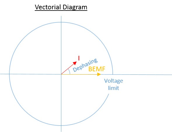
When it comes to drives for high-speed applications, always check if the motor you’re considering has a field-weakening mode. Field-weakening mode manages the phase advance between the current and the back electromotive force (BEMF) of the motor in accordance with the power requirement.
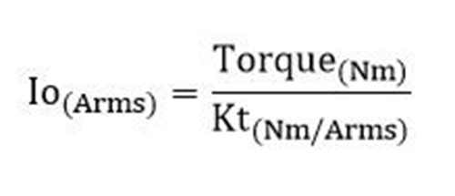
Select the drive size that provides enough rated current (Io) to the motor in order to generate the maximum torque needed. To calculate this current, divide the desired torque by the torque constant (Kt) of the motor. This is expressed in Nm/Arms.
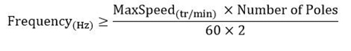
Take note that as the size increases, the output frequency has a nasty habit of decreasing. For this reason you should double-check the drive’s ability to provide sufficient frequency. Here, you should calculate the minimum frequency requested by the motor to reach maximum speed.
The results are best plotted in vector diagrams showing axe mode, field-weakening mode below the maximum voltage of the drive, and field-weakening mode beyond the maximum voltage of the drive.
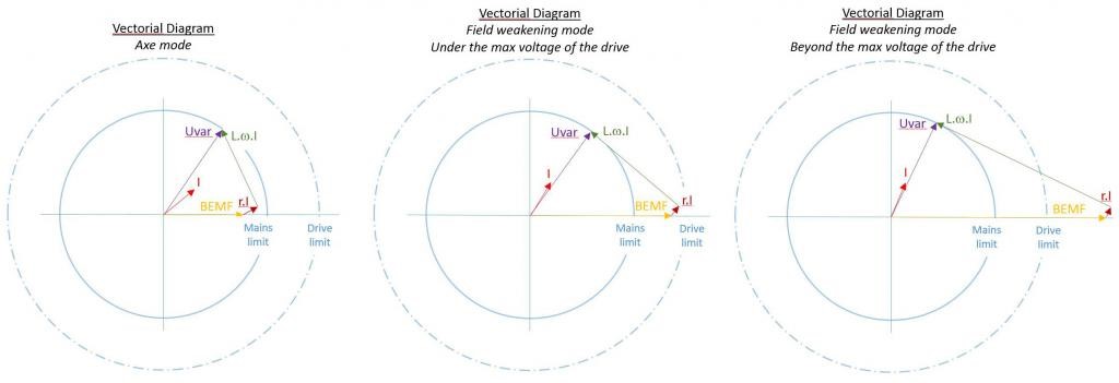
The latter will show if the BEMF is over the drive limit due the high maximum speed. In this case, a protection module has to be added. This is because, in the event of an incident or power supply failure, the motor can become a generator driven by the load inertia. Here, the BEMF is on the terminals of the drive and, at extreme speeds, the motor and the drive will be damaged by excessive voltage. A protection module will short-circuit the motor or clip the motor voltage accordingly. The protection module and the drive must be capable of withstanding the short-circuit of the motor current to ensure integrity. The motor, the drive, and the protection module have a maximum voltage limit of around 2000V.
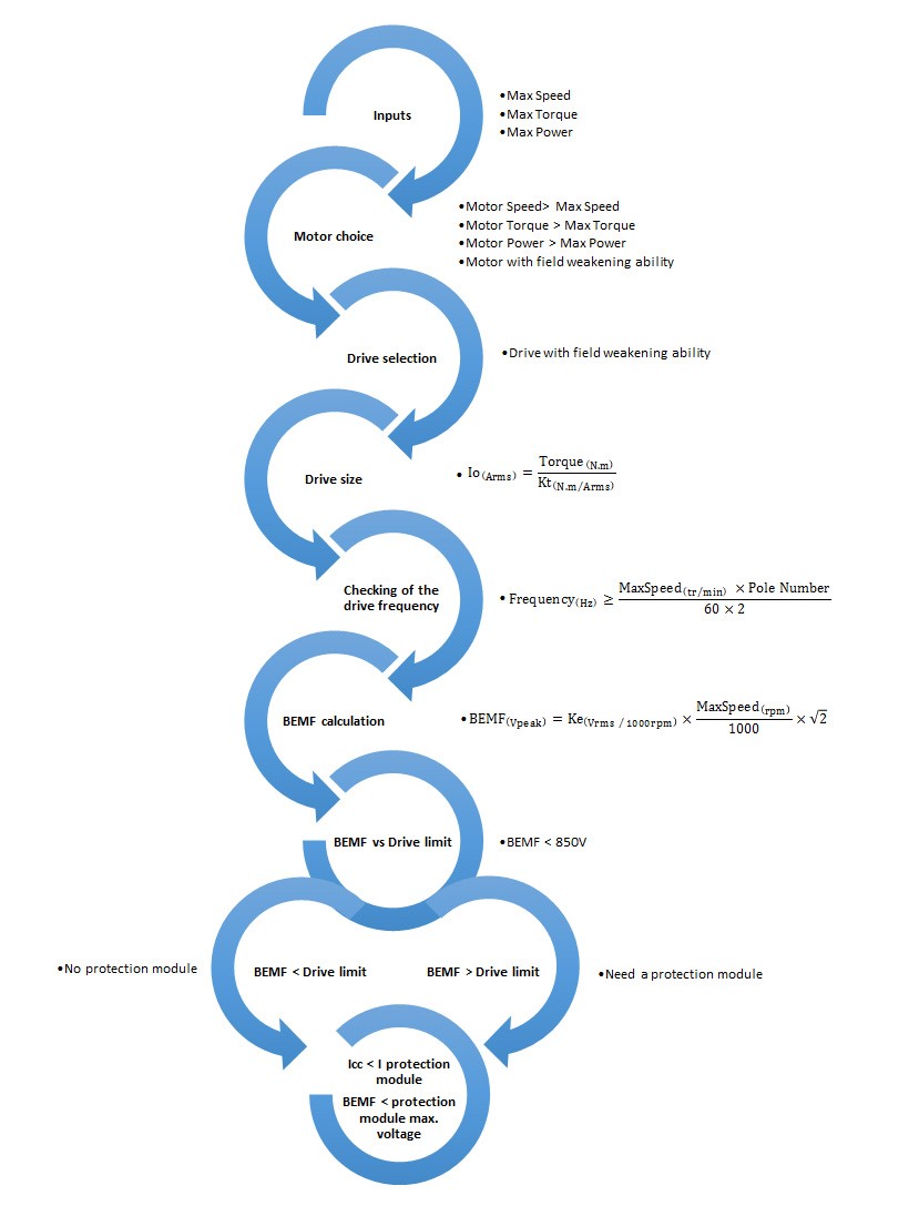
The following chart will guide you through the selection process:
This story originally appeared in the November/December 2016 print issue. You can read the digital edition here.
Filed Under: Rapid prototyping