In previous motion-sizing articles, we reviewed how to properly specify (using software) a ballscrew-driven motion axis. Then we reviewed how engineering teams can use a similar software-based approach for sizing rack-and-pinion-based servomotor-driven axes on the same five-axis gantry. Now we’ll explore the process for sizing the components (using that same software) for an electric-motor-powered axis based on chain and sprocket power transmission.
By Sixto Moralez • Regional motion engineer | Yaskawa America Inc.
Using software definitely eases the task of sizing axes run off chain and sprocket power-transmission drives. That’s because software lets engineers methodically enter the axis load, mechanical details, and system transmission type. Then it’s easy to modify the axis move profile to accommodate how fast the application needs to move in an editor screen — and (in the last step) pick a servomotor that can do the job.
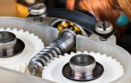
 Among the easiest motion-system designs to specify are those based on chain-and-sprocket power transmission — whether ultimately destined to output rotary or linear motion. In addition, chain and sprocket sets are often the most effective choice to drive linear motion axes. Recall from basic mechanical engineering that the main mechanical parameters in these assemblies are:
• The sprocket pitch circle diameter
• The chain mass and
• The sprocket and idler inertias.
Chain-and-sprocket power transmissions have efficiencies from 95 to 98% — so are slightly less efficient that competing alternatives. However, there are many applications that don’t require particularly tight tolerances or efficiencies. Let’s explore this in more detail with one example.

Chain-and-sprocket design load calculation: This example will focus on moving a load mass of 200 lb up and down to carry material from the bottom to the top, and vice versa. This load will always be present — and we can account for it in our sizing software.

Chain-and-sprocket design friction calculation: For the friction number, because cast iron is the most common and economical material for sprockets and chains are generally made from carbon or alloy steel, the Materials A and B can be selected as such:


Chain-and-sprocket design inclination calculation: Because this is a vertical application, we use the inclination tab within the software enter 90° to account for gravity.

The chain-and-sprocket design mechanism can be defined by three parameters.
- Sprocket pitch circle diameter: This is the measurement of the diameter about which the chain moves. It is used to calculate a rotational to linear ratio. For our example, 4.01 in. will equate to 12.598 in. of linear travel:
4.01 · π = 12.5977 in.
- Power-transmission chain mass: The mass of the chain itself is typically included in the load mass of the entire object being moved. However, it can be separated out and entered here.
- Power-transmission sprocket inertia: This is the inertia of the mechanism that will move the load mass. Again, sizing software will assist in finding this number … and the engineer need only enter a few sprocket details.

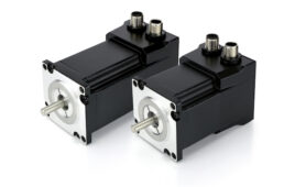
Now consider the power-transmission assembly as a whole. The transmission of a motion system represents everything between the electric motor’s output shaft and the mechanism it’s driving. This power-transmission driveline can be as simple as a gearbox or as complex as a serpentine-belt pulley system running over multiple idlers and driven axes. For these applications as well as our example chain-and-sprocket setup, Yaskawa’s gearmotors offer an easy integration solution.


The Sigma-7 Technical Supplement can be downloaded via this yaskawa.com deep link. The transmission can be entered as such with the specification sheet for the particular model of gearbox:
![]()
![]()
The next step is to account for the axis’ required move profile. As with all move profiles, it’s important to account for a forward (up) move and a reverse (down) move. Moving the axis in the upward direction requires the use (in design calculations) of the mass load to determine the speed and torque required. Of course, when the axis moves its load downward, the mass payload and gravity are the determining values. Any axis involving a vertical drop will likely incorporate regenerative energy in the motion system … and the servo amplifier (in our example case, a Yaskawa SERVOPACK) must accommodate this energy. Otherwise, an external regenerative resistor will be required.
Assume our move profile involves a 4 in. per second velocity over a 50-in. stroke to give:

After accounting for the design’s move profile, the next step is to select a servomotor. This servomotor should be capable of handling the system’s speed, torque, and inertia. For our example case, Yaskawa’s Sigma-7 SGM7J Series at 400 W can handle the load and move profile.


The last consideration for this design is regeneration. Because our example application must handle the load moving upward and downward, the deceleration makes for energy returned to the drive as regenerative energy. Seen below is the amount of energy for moving the 200 lb load downward at 4 in. per sec. Notice how the 400-W Yaskawa Sigma-7 SERVOPACK has no built-in regenerative resistance — so this application will require an external regenerative resistor.


Related: How to size a rack-and-pinion system for a precision motion axis

Here we review how engineering teams can use a similar approach for sizing rack-and-pinion-based servomotor-driven axes on the same five-axis gantry. We’ll use manufacturer software to work through the application.
Related: Using software for designing and sizing motion-control systems
![]()
You may also like:


Filed Under: Drives (servo) + amplifiers, Motors • servo, Motion Control Tips