Today’s applications require that cylinders be pushed to move faster, use higher pressures, or last longer than ever before. In addition, they are expected to run with higher efficiency and minimal leakage. These conditions mandate that sealing systems work with optimum effectiveness.
Matching the required sealing solution to cylinder demands is a straightforward process. First, review the impact of the operating environment. Then factor in component layout, mating hardware and operating conditions to establish effective sealing. Here’s what should be considered whether your cylinders are moving faster, lasting longer or operating under stronger conditions.
Moving faster
Faster movement can have many ramifications:
–High speed extension or retraction rates
–Increased number of cycles in a given time
–Less dwell time between extension and retraction
–Increased acceleration and deceleration rates
Each of these scenarios affects the sealing system. They produce the potential for higher heat, more wear, pressure buildup and dynamic events, all of which must be addressed to create an optimum design.
Higher heat: As systems move faster, more heat is generated that affects the sealing system and thus the hydraulic cylinder.
This heat can be generated from:
–The dynamic effect of the seal or bearing in contact with the rod or housing which typically worsens with higher velocities
–The valving needed to move the cylinder faster
–The fluid, which has less time to cool
–Fluid breakdown or viscosity changes
–Fluid routing
Increased heat from faster movement adversely affects the hydraulic cylinder and the sealing system. For the sealing system, higher heat affects the friction, leakage control, and seal life. For the cylinder, the effect is on position control, energy consumption, life, and overall cost for a cylinder.
With position control, changes in the sealing system can cause the feedback system to overshoot or undershoot. Pumps need to work harder due to changes in fluid viscosity, causing decreased efficiency and thus higher energy consumption. Cylinder life is linked to sealing system life, which is affected by heat. Cost is affected by system life or downtime, decreased performance, and increased energy consumption.
To minimize the effects of high heat, initially there are two independent routes taken, one by the cylinder manufacturer to reduce the heat and the other by the sealing-system supplier to both reduce and minimize the effects of higher heat.
The cylinder manufacturer might take steps to ensure alignment for more uniform loading on the sealing system, minimize additional heat sources, maximize fluid cooling and ensure adequate fluid exchange near the seal. These are often the first steps to minimize higher heat around the sealing system.
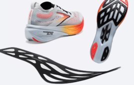
Sealing-system suppliers would typically investigate the bearings and seals. For bearings, the primary goal is to ensure that the design, material, and its location relative to the seals will be able to handle the heat, limit the amount of additional heat coming from the friction of the bearing itself, provide the necessary support for the seals, potentially aid in forming a fluid film under the seal, and stay within the system cost targets. Here’s an example of a ‘teardrop pattern’ used in some polymer bearings to assist in forming a fluid film under sealing system components.
For seals, the main emphasis is to investigate the use of materials and designs that can handle the increased heat; a secondary effort would be to lower the friction to decrease the temperature near the seal. Ways of doing this are to reduce seal contact stress, change the design to allow for a different footprint, adjust fluid film under the seal, or change the material.

A ‘teardrop’ pattern is often used in polymer bearings to assist in forming a fluid film under the sealing system components.
One example, which illustrates all four changes, is a newly designed U-cup seal. This design increases the temperature capability and lowers friction compared to a standard U-cup. The seal also contains a microstructure combined with back-pumping channels (see sidebar for definitions of specialized terms) on the dynamic seal-slide segment that ensure a constant lubrication film underneath the seal sliding surface and back-pumping across its entire pressure range. This configuration reduces friction and thus temperature near the seal.

New Zurcon U-cup seal handles higher temperature and lower friction than standard U-cup.
Although the sealing supplier and cylinder manufacturer can work independently to deal with heat from systems running faster, a team approach helps optimize the design. Here are some examples where cooperation between the sealing system supplier and cylinder manufacturer can develop a better system for applications with higher heat:
Proper surface finish. Unsuitable surface finish will not allow an adequate fluid film under the seal. Too smooth of a finish will not allow a sufficient fluid film under seals, while too rough will cause the seal to initially ride on the surface finish peaks and may change the surface finish or the seal.
Proper rod hardness and surface coating. Rod hardness and surface coatings have to be adjusted with surface finish. Too soft a rod and too thin a coating can allow the seal to alter the surface finish. Too hard a surface may damage the seal.
Maximize the load distribution on the bearing. Too high a unit loading will add to the system heat and limit life. The overall packaging envelope needs to be considered when determining proper bearing width and spacing.
Change lubrication pattern underneath the bearings. Adding grooves, cavity, patterns, or splitting the bearing will change lubrication pattern. These actions can minimize the frictional heat generation from the bearings and help keep a good fluid film for the seal to ride on.
Understand spacing and location of the bearing relative to the seals. Unsuitable location will not allow adequate support for alignment and will result in higher local loading of the sealing components, increasing heat.
Understand sealing system component layout and the effect on fluid film thickness to reduce friction. To reduce heat, the seals need to ride on a thick fluid film that can be back-pumped back into the system. Too few components can lead to leakage, while too many components will add cost and unnecessary heat from friction.
Understand fluid conditions. Changes in viscosity and potential fluid breakdown affect the fluid film that the seals ride. Too thin a fluid film will generate heat and friction. On the other hand, too thick a fluid film may result in excess leakage.
Understand potential hardware dynamics. Hardware ballooning is critical, as it changes the contact stresses of the seal, affecting the fluid film thickness. Other hardware dynamics due to heat, such as softening the bearing support, also must be addressed.
Higher wear is associated with faster cylinder movement. Such wear can be caused by:
–Time-related dynamic effect of the seal or bearing in contact with the rod or housing
–Poor lubrication conditions
–Increased impact of contaminates in the system
–Increased wear caused by higher heat changing the material properties
Wear adversely affects the position control, energy consumption, life, and overall cost of a cylinder. And, wear affects the friction, leakage control, and life of the sealing system. Cost may increase as wear may be severe enough to damage both sealing system components and mating surface hardware.
The cylinder manufacturer can ensure alignment and remove heat to reduce wear. Benefits come from minimizing contamination, tightening tolerances, and minimizing conditions such as hold under pressure and dithering.
Sealing-system suppliers know that wear is a function of surface finish, running surface hardness, fluid, material, design, velocity, temperature, and loading. The nearby chart shows test results on materials in two operating conditions, with the only change being the fluid conditions. As the operating conditions change, the wear factor can be completely different, and thus the choice of material may change.

Wear factor on material under differing fluid conditions.
As cylinder maker and sealing-system vendor work together, they can take these steps to reduce the impact of wear.
–Ensure proper surface finish
–Ensure proper rod hardness and surface coating
–Maximize the load distribution on the bearing
–Change lubrication pattern underneath the bearings
–Understand spacing and location of the bearing relative to the seals
–Understand sealing system component layout and the effect on fluid film thickness to reduce friction
–Understand fluid conditions
–Understand potential hardware dynamics
Pressure buildup: With systems running faster, pressure buildup has an effect on the sealing system. Pressure buildup can come in these forms:
–Short duration buildup (i.e. pressure spikes) caused by:
–Valving not responding fast enough
–Closing action of the valves
–Lack of appropriate accumulators
–Fluid film changing, allowing it to pass under the seal and not allowing it to enter back into the system, as the hydrodynamic pressure to feed back fluid is insignificant.
Whichever the scenario, pressure buildup affects life, leakage and friction on the sealing system, potentially causing these effects on cylinders:
–Load limitations. Seals cannot handle the pressure to move the load.
–Poor position control. Friction changes in the sealing system and this affects the feedback loop causing the potential for over and under-shoot.
–Shorter life. Due to pressure buildup the seals can extrude and wear at a greater rate, limiting life of the sealing system.
–More energy Consumption. Increased energy is needed due to the higher friction.
–Higher cost. Costs go up with increased energy consumption and downtime.
–Compromised safety. There is a potential for having pressure between seals with the system not pressurized.
Cylinder manufacturers can minimize potential for pressure spikes if they:
–Inspect valving to ensure proper speed and smooth closing actions
–Ensure appropriate pressure damping, such as appropriate size accumulators
–Ensure appropriate pressure relief capability
–Move the source of pressure pulses away from the sealing system
Sealing system suppliers counter pressure buildup through design, but in different ways. For systems where rapid pressure buildup could occur, sealing systems are designed to knock down the pressure prior to the primary seal and to allow for fluid to be pumped back into the system. A buffer seal that might be used in this situation is shown below.
Another alternative, to allow the pressure to build up and then relieve it without damaging any components, is done by various pressure-relieving product designs. The illustration below shows a seal with an integrated check-valve function that automatically releases the inter-seal pressure when it is higher than the system pressure. As the pressure builds up between the seals, the O-Ring moves, allowing pressure relief through the pressure-relief channel.
As mentioned earlier, the cylinder maker and sealing system vendor will have the best results when they combine efforts to:
Ensure proper surface finish, rod hardness, and surface coating.
Inappropriate finish can allow too much fluid film to pass under the seal, leading to pressure buildup between seals. Conversely, inappropriate finish will not allow enough fluid film, causing excessive friction and wear.
Understand sealing system component layout. To reduce the effect of pressure buildup, a buffer seal or pressure-relieving seal may be recommended.

Buffer seal offers one way to counter pressure buildup.
Understand fluid conditions. If the fluid viscosity is too high, the fluid may pass under the seal and not be allowed to reenter back into the system. Alternatively, lower viscosity fluid may not allow the pressure to build up between seals. However, this might not provide enough lubrication, causing higher heat and more wear.
Understand assembly. With pressure buildup, higher strength materials, which are less pliable, and added components such as backup rings, may be the preferred direction.
Dynamic events: With cylinders moving faster, a variety of dynamic events must be addressed:
–Starting/stopping
–Dithering
–Ballooning
–Vibration/Noise
These effects result from such factors as system plumbing (valving and accumulators), filters, component connections, or momentum of the system running faster. For a cylinder manufacturer these effects equate mainly to life, position control, energy consumption and cost; and can be reduced by focusing efforts on cylinder design, valving, accumulators and filters to minimize the starting/stopping and dither. For vibration/noise the concentration is on:
–Increasing vibration/noise absorption
–Minimizing alignment issues for more uniform loading of the sealing system
–Keeping tighter tolerances, which reduces variations for which the sealing systems must compensate.
Meanwhile, sealing-system suppliers focus on sealing system life, friction, and leakage control through these areas:
–Enabling the sealing component to handle a wider variety of tolerance conditions like ballooning.
–Ensuring adequate fluid film is possible under the seal in all conditions, which is best handled through design and sealing component layout. Adequate fluid film thickness lowers friction, heat and wear of the sealing system.
Use of materials that are strong enough to handle higher impact or dithering conditions. An example is specially formulated materials that operate in a dithering environment without affecting the mating hardware.
Ensuring that the designs can track the dynamic components throughout the cylinder duty cycle even with high-vibration conditions.

Another pressure-relieving seal. As pressure builds, the O-ring moves, allowing pressure to be relieved through the pressure-relief channel.
Again this calls for a joint effort between the cylinder manufacturer and sealing system supplier to deal with the dynamic effects of cylinders moving faster. Some areas to consider jointly are:
Proper surface finish, rod hardness and surface coating. Inappropriate surface finish and rod hardness will not allow an adequate fluid film under the seal and not allow the seal to handle all operating conditions.
Load distribution on the bearing. Excessive loading may add to system noise and vibration rather than dampening them.
Bearing location relative to the seals. Unsuitable location doesn’t provide support for alignment and causes higher loads on seals, vibration and noise, and inability for the seals to track the dynamic surfaces.
Sealing layout and fluid film thickness. An adequate fluid film under the seal in all conditions allows the sealing system to cope with the dynamic effects of starting/stopping, dithering, and vibration/noise.
Fluid conditions. Changes in viscosity and potential fluid breakdown affect the fluid film thickness: too thin will result in poor sealing performance, while too thick may result in leakage.
Trelleborg Sealing Solutions
www.trelleborg.com
To be continued…
Look for “lasting longer” and “operating under stronger conditions” in the next article in this series, appearing in a future issue of Design World.
Definitions
Backpumping is the action in which fluid film passes between the seal and the mating dynamic surface during an extend stroke and then is returned to the system during the retract stroke through hydrodynamic principles.
Ballooning describes expansion of the cylinder housing caused by either thermal or pressure
situations.
Creep is an increase in seal deformation under a constant pressure/load.
Dieseling is the sudden pressure increase in an oil-air mixture in which the air bubbles ignite.
Dithering occurs when the dynamic surface moves a very short distance and at high frequency, which drives out fluid film under the seal to create higher friction or wear or creates little fluid exchange, leading to higher heat.
Explosive decompression refers to an event in which high pressure can permeate the surface of the sealing material. When the system pressure is rapidly released, the sealing component can experience a sudden degradation or complete failure caused by the fluid trapped in the sealing material suddenly expanding and ‘exploding’ the material.
Hold under pressure is the operating condition where a load is held for an extended period of time without any rod movement. This puts the seal in a static condition under high pressure which
increases the likelihood for permanent deformation and extrusion and eliminates or reduces the fluid film under the seal.
Hydroplaning occurs when hydrodynamic forces lift the sealing contact off the dynamic
surface and allow fluid to pass under the seal.
Stress relaxation refers to decay of sealing stress over time when placed under a constant strain/deformation.
Filed Under: Hydraulic equipment + components, Seals • O rings, FLUID POWER, Materials • advanced, Seals

Tell Us What You Think!