By Simon Pata
Simon Pata is Product Line Manager at Portescap, a Danaher Motion Co., West Chester, Penn.
Ironless motors may not be on your top-ten list of choices, but check out these dynamics before making your final decision. You might be surprised at the results.
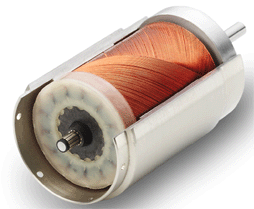
Brushed dc coreless motors have air core armatures, so they can reach high speeds in a matter of only milliseconds with about 90% efficiency.
Compared to conventional iron-core, brush-type dc motors, the ironless types have no iron losses, low friction, and acceptable thermal dissipation, which make them extremely efficient. The design of the low-inertia rotor is the key to rapid acceleration and fast reaction time. In addition, their linear torque-speed characteristics fit well with simple drive circuits. They should be especially considered when designing low-power, battery-operated equipment, such as pagers, model trains, and hand-held tools.
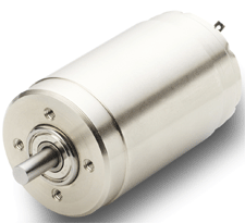
The name coreless (or ironless) refers to the motor construction. These motors, unlike most other types of motors, have no iron core-armature in the rotor. Special skewed or honeycomb patterns are used to wind the rotor coils to ensure mechanical strength and evenly distribute the magnetic flux for all coils in the rotor winding. This results in maximum torque and smooth rotation. Because it has no iron core to support the windings, they are typically held together by epoxy. Some designs use a plastic frame. Depending on the rotor geometry, ironless motors can be cylindrical or disc shaped. The stator is often made of ALNiCo, samarium-cobalt, or Neodymium magnets.
The commutators and brushes of smaller ironless motors are usually made of precious metals such as silver, gold, platinum, or palladium. They have low friction and generate little electrical noise. Larger motors often have copper-graphite commutation systems, which can handle high-density commutated current. Due to the absence of iron in the rotor, ironless motors have low winding inductance and thus lower levels of sparking between the brush and the commutator than conventional motors. Arcing normally produces electro-erosion and shortens the motor’s service life.
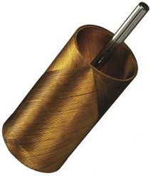
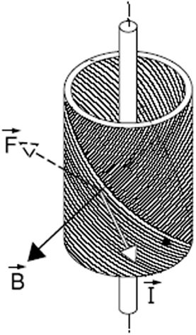
The hollow, basket-shaped rotor surrounds the permanent-magnet stator. The magnetic field with flux density B created by the stator interacts with the current I in the rotor winding creating rotational force F.
Because the weight of the ironless rotor is significantly less that the weight of a comparable rotor in a cored dc motor, ironless motors accelerate and decelerate much faster. Low-inertia motors can also present a significant advantage for applications with hard stops; the rotor is less susceptible to damage. Small, light-weight motors are extremely critical for applications such as airspace and military systems, hand tools, and medical equipment.
Absence of cogging (torque ripple) is another benefit critical for many applications. In a conventional cored motor the rotor has a tendency to assume a certain position due to the uneven reluctance of the slot wound laminated iron rotor. Because the ironless motors have no core, the torque is more evenly distributed during any position of the rotor. The rotor can be positioned more accurately and the motion at low speed is much smoother.
Since it has no eddy current losses, an ironless motor is more efficient than a comparable cored motor. At a no-load condition the current of an ironless motor drops to just a few milliamps (tens of milliamp s for larger or lower voltage models). This can be a big advantage for battery powered equipment where the motor load varies from no-load to nominal-load conditions.
For many portable electronic devices, the low level of electromagnetic interference produced by ironless motors can be quite critical. Motor commutation systems are a major source of EMI. Reducing the winding inductance of ironless motors results in less arcing when the electrical contact is broken between the commutator segment and the brush. Lower levels of sparking generate less EMI.
Unfortunately, ironless motors can overheat when the maximum load is exceeded for more than just a short time. Because the motor has no metal core to act as a heat sink for the rotor windings they heat rapidly due to overload, including stalling. The adhesives that hold the windings in place can relax and the rotor might fly apart. To help cool the windings the motor casing often contains openings for convection air cooling, but coreless motors cannot tolerate overloads as well as cored motors.
Design guide
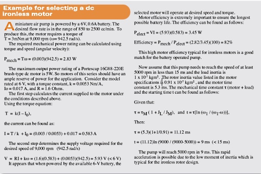
When the motor is voltage driven, the following equations contain detailed design parameters that are necessary to take full advantage of the coreless technology.
An ironless rotor motor can be represented by the following simplified diagram:
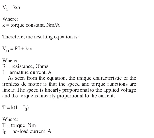
The voltage induced in the rotor (back EMF) is proportional to the angular velocity of the rotor:
![]()
Where:
![]()
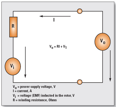
Motor manufacturers normally specify three constants: back EMF constant, torque constant, and velocity constant. If these three constants are expressed using the proper units their values are equal. So, substitute the torque constant for the back EMF constant in the equation.
Calculating Mechanical Power, Electrical Power, and Efficiency:
The electrical power applied to the motor equals the mechanical power produced by the motor plus the power dissipated as heat. At a given input power, more mechanical power becomes available to drive the load as the losses diminish.
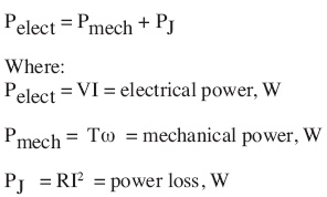
At a given input power, more mechanical power is available to drive the load as the losses diminish.
The motor efficiency is defined by the ratio of the mechanical power and the electrical power:

The Torque-Speed Curves graph is a visual representation of the interdependency of various motor characteristics. It shows motor efficiency, speed, mechanical power, and armature current as functions of torque. The three speed curves were plotted at different supply voltages and show linear dependency between the supply voltage and the speed. The following observations can be made:
• The current is proportional to the motor torque.
• The speed is proportional to the supply voltage.
• The maximum efficiency occurs at high speed.
• The mechanical power reaches its maximum when the load torque is equal to half the stall torque.
To ensure long service life the maximum armature temperature must not be exceeded. For example, the maximum rated coil temperature of a certain motor is 100° C. The equations below show how to determine the rotor temperature.

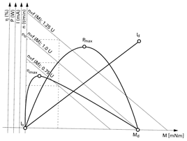
This is a visual representation of the interdependency of various motor characteristics. The X-axis represents the torque. The efficiency, power, current, and speed axes are aligned with the Y-axis.
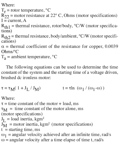
Although coreless motors have been widely used for forty years, this technology is steadily advancing through motor manufacturers’ efforts to incorporate new materials and perfect the magnetic and mechanical designs. In the world of miniature motors the precision, efficiency, smooth operation, light weight, and compact size of ironless dc motors are hard to beat.
Portescap, a Danaher Motion Co.
www.portescap.com
::Design World::
Filed Under: Motion control • motor controls, Motors • dc

Will be interested in how coreless motor are being wind
Is there machine supplier who can do that..
What is the jig and fixture required
Yes, coreless motors are typically wound by automated machines. Most of the motors manufacturers build these machines in house as those have a very complex design and are thought to provide a competitive advantage