In the past digital systems were 5V and analog ones +/-15V or +/-12V. Nowadays analog systems are more likely to be single supply 5V, 3.3V or lower and digital circuitry is likely to be 3.3V, 2.5V, 1.8V, 1.2V or something in between. You might also have LVDS, DDR or other differential or single ended standards to interface to. This is fine when all the logic runs at the same voltage or when you have two compatible interfaces using the same supply voltage but when designing a complete mixed signal system you often end up having to get two chips with incompatible interfaces or different voltages connected to one another. This can be as simple as connecting a 5V chip to a 3.3V one but it still needs some thought if the system is to perform correctly at the necessary speed and power consumption.
A crude but usable circuit can be made with a transistor and couple of resistors provided you understand the limitations:
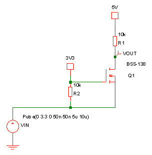
It actually will work bi-directionally but is quite slow in either direction and consumes significant power due to the pull-up resistors:

As can be seem from the simulation, it has a very slow rise time so is only of use for low speed systems although the resistor values can be reduced to increase the speed.
Some microcontrollers have 5V tolerant input-outputs although the word “tolerant” is the clue that this is not necessarily as sophisticated as you might want. In the case of the Microchip PIC microcontrollers running at 3.3V or lower they have a 5V tolerant input and they can drive a 5V signal as an output by configuring the output as open drain and adding a pullup resistor to 5V. Again, it will suffer from limited speed due to the passive pullup rather than the active PMOS pullup of a CMOS circuit. Also, be careful because usually not all pins are 5V tolerant, just some of them.
A chip such as the Texas Instruments SN74LVC245A is a CMOS level shifting transceiver which operates from 1.65 to 3.6V and accepts input signals up to 5.5V. However, while it is bi-directional (using a direction control pin) it cannot output a signal higher than the supply voltage so if you are interfacing a 3.3V system to a 5V system then the signal to the 5V system will not exceed 3.3V.
There are chips for level shifting I²C bus signals such as the Texas Instruments PCA9306 but that is a specific interface that relies on pullup resistors anyway and so is not very fast. It would be fine for the job it is design to do though – and I²C level shifter.
The MAX3372E and similar devices provide true bi-directional level shifting (without a direction pin) up to 8Mbps or higher depending on the voltage levels of the two systems. Not bad compared to a simple transistor approach, and power consumption is reasonable.
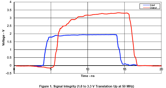
The Texas Instruments LSF0101 range are bi-directional (without a direction pin) and work up to 100MHz but that relies on a low value pullup resistor of around 160 ohms. A typical waveform from the datasheet is shown below:
By now, assuming you haven’t already looked into level translation before, you will realize it is not as simple as you might have hoped it would be!
You could translate between 3.3V and 5V in one direction (up) by using a buffer with TTL thresholds rather than CMOS ones. That would switch above 2V which is easily achievable from a 3.3V logic signal. The problem with that approach, apart from only being possible in one direction, is that holding a TTL level 5V CMOS IC with the input at 3.3V could result in high power consumption. CMOS logic takes almost zero power when not switching because it consists of PMOS and NMOS transistors where only one is turned on at any one time, except during transitions where brief clashes will occur. By holding an input at 3.3V on a 5V chip you could have both the PMOS and NMOS input transistors on simultaneously to a certain extent. This will not damage the device as it must be able work with an input held at 2V indefinitely, but unless specified in the datasheet you will not necessarily get zero static power in that situation.
For example, the Texas Instruments SN74AHCT1G00 single NAND gate has TTL thresholds, so above 2V is considered a logic high. However if you hold one input at 3.4V with the power supply at 5.5V the current can be as high as 1.5mA (figures from the datasheet).
So, when level shifting between circuits, take care, bearing in mind power consumption, signal direction and speed. If it is for a specific type of interface such as I²C, look for a chip specifically for that interface type. When you think you have found a good solution, double check you really have.
The post Level Shifting Digital Logic Signals appeared first on Analog IC Tips.
Filed Under: Commentaries • insights • Technical thinking, MOTION CONTROL