Design World

  • Home
  • Technologies
    • 3D CAD
    • Electronics • electrical
    • Fastening & Joining
    • Factory automation
    • Linear Motion
    • Motion Control
    • Test & Measurement
    • Sensors
    • Fluid power
  • Learn
    • Ebooks / Tech Tips
    • Engineering Week
    • Future of Design Engineering
    • MC² Motion Control Classrooms
    • Podcasts
    • Videos
    • Webinars
  • LEAP AWARDS
  • Leadership
    • 2022 Voting
    • 2021 Winners
  • Design Guide Library
  • Resources
    • 3D Cad Models
      • PARTsolutions
      • TraceParts
    • Digital Issues
      • Design World
      • EE World
    • Women in Engineering
  • Supplier Listings

LiftWalker uses ball-scew actuator to help patients leave wheelchairs

By Mike Santora | June 2, 2015

Share

The new LiftWalker from medical manufacturer Ideomotion is a stainless-steel frame with 12 V actuators that run off two rechargeable Nickel-Metal-Hydride batteries. Made in the U.S., the walker assists people from 3 ft 6 in. to 6 ft 6 in. tall and up to 300 lb with juvenile, preschool, and X large models. An easy-adjust thoracic prompt fits to the user in moments and comfortably lifts them to standing in a few seconds.

Thigh prompts make standing possible for almost anyone. Patients use their biceps, chest, back, stomach, and leg muscles simultaneously to engage the frame, increasing strength. This is safer than being pulled by an attendant or caregiver.
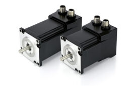
The New LiftWalker uses Motion Systems Corp. Model 85199 ball screw actuators to pull the patient up from sitting.

A ball cage within the nut ID cams up against stop pins at each end of travel to initiate freewheeling and linear advancement stops. The stop pins are mounted in the screw thread and are factory installed for the specified stroke. This design generally eliminates the need for externally mounted limit switches. Motor speed reduction to drive the Ball Screw is by a single stage worm gear reducer. The housing is die cast aluminum alloy. A molded neoprene coupling with steel inserts couples the motor shaft to the worm shaft and provides protection against shock loads. The worm shaft runs in an oilite bearing at the motor end and a ball bearing at the opposite end. The Ball Drive is mounted in a ball bearing at the output side of the gear reducer which takes axial thrust loads, and an oilite bearing at the opposite end. Both the worm and gear are heat treated steel for long wear life. An aluminum cover tube with a quad ring seal at its outboard end encloses the screw.

“The ball drive actuator has sufficient advancement speeds and custom stroke,” said Erik Wolf, president, Motion Systems Corporation. “With the Ideomotion walker, the actuator provides the mechanical muscle to help a wheelchair-bound person stand up and walk.”

Motion Systems Corporation

www.newliftwalker.com

Motion Control Tips


Filed Under: Motion Control Tips
Tagged With: motionsystems
 

Related Articles Read More >

Schneider Electric launches Universal Automation Discovery Packs to foster industrial innovation
Encoders from SIKO support Industrial Ethernet
Draw-wire encoders from SIKO measure position, speed and inclination
Incremental encoders configurable via NFC (near-field communication)

DESIGN GUIDE LIBRARY

“motion

Enews Sign Up

Motion Control Classroom

Design World Digital Edition

cover

Browse the most current issue of Design World and back issues in an easy to use high quality format. Clip, share and download with the leading design engineering magazine today.

EDABoard the Forum for Electronics

Top global problem solving EE forum covering Microcontrollers, DSP, Networking, Analog and Digital Design, RF, Power Electronics, PCB Routing and much more

EDABoard: Forum for electronics

Sponsored Content

  • Global supply needs drive increased manufacturing footprint development
  • How to Increase Rotational Capacity for a Retaining Ring
  • Cordis high resolution electronic proportional pressure controls
  • WAGO’s custom designed interface wiring system making industrial applications easier
  • 10 Reasons to Specify Valve Manifolds
  • Case study: How a 3D-printed tool saved thousands of hours and dollars

Design World Podcasts

May 17, 2022
Another view on additive and the aerospace industry
See More >
Engineering Exchange

The Engineering Exchange is a global educational networking community for engineers.

Connect, share, and learn today »

Design World
  • Advertising
  • About us
  • Contact
  • Manage your Design World Subscription
  • Subscribe
  • Design World Digital Network
  • Engineering White Papers
  • LEAP AWARDS

Copyright © 2022 WTWH Media LLC. All Rights Reserved. The material on this site may not be reproduced, distributed, transmitted, cached or otherwise used, except with the prior written permission of WTWH Media
Privacy Policy | Advertising | About Us

Search Design World

  • Home
  • Technologies
    • 3D CAD
    • Electronics • electrical
    • Fastening & Joining
    • Factory automation
    • Linear Motion
    • Motion Control
    • Test & Measurement
    • Sensors
    • Fluid power
  • Learn
    • Ebooks / Tech Tips
    • Engineering Week
    • Future of Design Engineering
    • MC² Motion Control Classrooms
    • Podcasts
    • Videos
    • Webinars
  • LEAP AWARDS
  • Leadership
    • 2022 Voting
    • 2021 Winners
  • Design Guide Library
  • Resources
    • 3D Cad Models
      • PARTsolutions
      • TraceParts
    • Digital Issues
      • Design World
      • EE World
    • Women in Engineering
  • Supplier Listings