By KAVEH AZAR, Ph.D., President and CEO of Advanced Thermal Solutions, Inc. (ATS).
One of the challenges in LED lighting is the alignment of the cooling system with the deployment site requirements. LEDs do not present a new heat transfer challenge that has not been dealt with before. But integrating the right cooling technology for the thermodynamics is key.

LED lighting is one of the world’s fastest growing markets. Light-emitting diodes (LEDs) are a disruptive technology for the standard lighting industry and the products that we have enjoyed for decades. Much of this advantage stems from their energy usage and conversion rates. Additionally, LEDs enable more direct control of light output compared to fluorescent and incandescent lights. Superior control of light output from LEDs is one of a growing list of differentiators for applications ranging from cosmetics to industry to residences and street lights. But before widespread adoption can occur designers must understand the relevant properties to consider for development so they can provide a return on investment for customers.
Solid-state lighting, another name for LED lighting, is identical to other electronic devices in that their junction temperature determines longevity and proper operation. Cooling technologies for effective LED thermal management are available and are being deployed across the electronics industry. LEDs do not present a new heat transfer phenomenon that has not been dealt with before. The main challenge for LED lighting is integration of the right cooling technology for the deployment environment and user.
When it comes to the visible light range an LED is about three times more efficient than a comparable incandescent light, Figure 1.
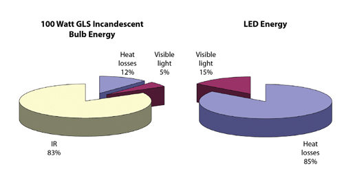
Figure 1: Power usage of an LED and an Incandescent light bulb.
LEDs generate heat and need to be cooled, but their light output from the same power is more effective than from traditional incandescent lighting technology.
How Heat Affects LED Response
The heat generated by an LED, and how it affects the control of an LED’s response, makes cooling a primary concern. Because LEDs are semiconductor devices their light output is directly affected by temperature. Figure 2 shows the effects.
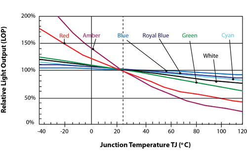
Figure 2: Effect of semiconductor junction temperature on the light output of different color LEDs.
The light output declines as the LED junction temperature increases. Blue is the least impacted color, experiencing only a few percentage points of variation over a wide temperature range, while amber and red vary the most. Each color is affected differently by temperature and the swing in light output is measureable and visible. This includes the low temperature ranges that are most common to today’s lighting applications.
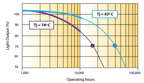
Figure 3: Useful life of high-brightness white LEDs at different operating temperatures.
Figure 3 shows the temperature effect on the L70 lifetime for a sample of commercial white LEDs. As seen in Figure 3, if a device’s junction temperature is reduced from 74° C by 11° C to 63° C, the L70 increases by 22,000 hours. Conversely, raising an LED’s temperature can have detrimental effects to operational lifetime. A rising temperature directly affects an LED’s forward voltage, causing it to decrease. This can increase the load on the components that drive the LED, increasing their temperatures, which shortens their life expectancy.

Figure 4: Effect of temperature on the wavelengths emitting from an LED.
A temperature increase will also cause the LED wavelength to change, as shown in Figure 4. The change in the wavelength can cause an orange LED light to appear as red. White LEDs may appear with a tint of blue. Excess heat won’t just disrupt colors. As with other semiconductor devices, if the thermal situation is not managed it will cause the LED to fail. Therefore, as with most electronics, the fundamental limits of LED performance are driven by thermal management.
Understanding LED Heat Transfer
While the function of LEDs hasn’t changed, their packaging has gone through major upgrades over the past few decades, which has advanced thermal performance. These improvements in packaging the LED assembly have reduced the thermal resistance from the semiconductor die to the exterior of the package, as seen in Figure 5. The lower the thermal resistance within the packaging, the greater the flow of heat away from the die for a given temperature difference. All else the same, the result is a cooler LED.
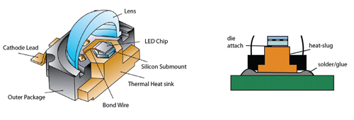
Figure 5: LED packaging – Use of a heat slug to carry heat from a semiconductor device to a printed wiring board (PWB).
The top surface of an LED is covered by its lens, which must be exposed for emitting the light. So, thermal management must be applied elsewhere. Today’s LEDs strive to transfer heat as efficiently as possible from the backside of the device to the controlling printed wiring board (PWB). Usually the die is attached to a heat slug that is interfaced to the PWB.
Designers try to minimize the contact thermal resistance between the heat slug and the PWB. These measures include the use of a thermal interface material, soldering (as long as there is electrical isolation), and more recently, constructing the whole LED structure on the PWB. When the LED is constructed on the wiring board, heat can be transferred to the non-component side of the PWB in different ways. Methods include the use of filled vias, heat slugs within PWB, adding a copper layer, and graphite foam. Once the heat enters into the PWB it is conducted to the backside (non-LED side) for dissipation into the ambient by natural convection or with an active cooling system.
Cooling Options
As with other semiconductor devices, there are many cooling options. They range from using a simple copper plate or heat sink to spread and dissipate heat to installing sophisticated cooling systems that contain liquid or refrigerant.
Cooling methods can be broadly divided into passive and active systems. Passive systems by definition have no active components, such as a heat sink. An active component could be a fan-cooled heat sink or a thermo-electric device (TEC). TECs are typically referred to as a Peltier device or semiconductor refrigerator. Active systems typically include a power-dependent component to assist with the cooling– this can be a fan, pump, phase-change material, or TEC.
Some driving questions should be raised when selecting an LED cooling system:
•Cooling effectiveness – will it yield the desired junction and temperature uniformity across an array of LEDs?
•Cost effectiveness – does the combination of the LED and the cooling system make the deployment of the system economically feasible?
•Deployment site – will the cooling method also add acoustic noise that could be undesirable?
•Power consumption – would power needed for the cooling system mitigate any savings attained by using LEDs in place of traditional lighting systems?
•Reliability – will the cooling system last, and will it require regular maintenance?
•Environmental friendliness – what is the carbon foot print of the cooling system – from deployment to disposal?
Considering the above criteria, the simpler the cooling system usually means the more desirable its deployment. If we can provide the required cooling and temperature uniformity with a simple copper or aluminum plate, and weight is not an issue, that will be the desired solution. But when higher levels of illumination are needed, the power dissipation will also be higher. Therefore, the cooling system must be carefully matched to meet an LED’s performance requirements.
The deployment site is a major consideration. Will the cooling system be suitable where the LED is installed? Imagine an LED street light with an active cooling system. Its fan may fail due to time and temperature and will need replacing for the LED to work properly. There then needs to be intelligence in the street light that will let a central office know if the fan has failed and shut that LED off until repairs are made. This combo of fan, monitoring system, and maintenance might counteract the cost gains from using LED lighting. So, designers may need to find a passive cooling system.
A wide variety of active LED cooling systems have already been deployed successfully in the electronics industry. One example is the use of synthetic jets to generate airflow inside an LED’s housing. Figure 6 shows a Nuventix Synjet being used for LED cooling.

Figure 6: Synthetic Jet Packaging for cooling of high power LED light fixture.
Although the Synjet does not have a blade like traditional fans, it provides air movement by creating oscillation via a diaphragm, Figure 7.

Figure 7: Synthetic Jet Cross Section showing an oscillating diaphragm to create air movement.
Cooling options in this broad category include:
•Piezo fans – used for local cooling in lower power applications where a piezo fan creates local flow and improves the heat transfer coefficient over natural convection-cooled LEDs.
•Fan-sink – a fan is placed on top of a heat sink that is attached to the back side of the PCB housing the LEDs.
•Jet impingement – air is directed on the hotspots on the backside of the LED array to provide more effective cooling than fan-sink.
•Liquid cooling – a coldplate is attached to the PCB carrying the LEDs (Figure 8). The plate is attached to a looped system that includes a reservoir, liquid-to-air heat exchanger and a pump. These systems are typically used where very high power lighting is required to justify their deployment.
•Refrigeration – in a refrigeration system, the evaporator is placed on the backside of the PCB housing the LEDs. As with liquid cooling the application of such an elaborate system depends on the essential need for the LED lighting.
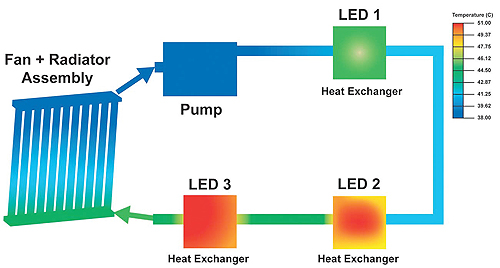
Figure 8: Schematic of a liquid-cooling system for an LED display application.
There are two important factors that all designers of LED lighting must first consider: thermal contact resistance and spreading resistance. From a cooling standpoint, the contact resistance where an LED touches the PWB, or where an LED-PCB unit contacts the cooling system must be minimal, regardless of whether passive or active cooling is used. Contact resistance can be lessened with thermal gap fillers, improved fabrication processes (e.g., flatness), and integrated construction of the LED and cooling system. A good designer will ensure that all contact resistances on the heat transfer path from semiconductor to the final ambient are minimized. The goal is to have the least-hindered flow of heat and minimization of temperature gradients underneath the LED.
Because LEDs are discrete heat sources attached to larger heat sinks or cold plates, thermal spreading resistance plays a major role in effective cooling. Depending on design and material selection, spreading resistance is often the major impediment to the desired flow of heat. Regretfully, this is often overlooked and the result is the installation of more complex cooling systems than needed. Understanding of flow of heat from the source to the sink, such as ambient, and minimizing thermal spreading resistance can be the difference between a simple heat sink and a more elaborate cooling system.
Much like the rest of product engineering, the challenges facing LED lighting designers is the alignment of the cooling system with the deployment-site requirements and its market acceptance. Imagine entering a room in your house where LED lighting is deployed and the room is saturated with fan or synthetic jet acoustic noise. The noise from your PC or your HVAC system is uncomfortable enough; now imagine the sound if there are also 12 LEDs cooled by air-movers. The greatest challenge confronting LED lighting designers is probably not the cooling technology – it’s readily available – rather it is the packaging of that cooling technology that will render the LED lighting a viable choice compared with other lighting options.
Discuss this on The Engineering Exchange:

Filed Under: Lights • signal lamps • indicators, ELECTRONICS • ELECTRICAL
Tell Us What You Think!