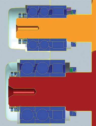
In compressor applications, the locknut can play a key role in establishing the clearance between the rotor and the compressor housing, where too little clearance causes seizure, while too much reduces compressor efficiency, due to leakage around the rotor body.
Spieth locknuts deliver accurate rotor positioning and reliable thrust bearing retention on compressors, shafts, spindles and other industrial/commercial applications.
While the standard Spieth locknut configuration had considerable appeal for the application, several design refinements were deemed beneficial for a particular compressor application. “We liked the positive locking feature without washers and keys, plus the locknut’s ability to support extreme thrust loads by providing full 360º contact around the thread flanks,” according to one application engineer.
 Key features that led to one compressor manufacturer’s selection of the Spieth product included:
• Square face to thread precision, for bearing reliability and compressor efficiency, due to accurate rotor positioning
• Lock screw adjustment does not reduce end clearance or negatively impact reliability
• Absolutely no locknut movement in operation
The full circumference contact of the Spieth locknut was designed to ensure the locknut would not back off, even when subjected to extreme shock loads. It further aligns its contact face with either a zero runout or, as needed, it can be adjusted to suit the inaccuracies of the in-line connecting components, thus compensating for minor errors of parallelism due to the stack-up of mating parts. Uneven bearing loading is thus compensated and its impact minimized.
The basic design of the adjustable locknut involves two axially arranged radial grooves, one from the outside and one from the inside, which result in a diaphragm-like cross-section to give the locknut a predetermined axial elasticity. The internal groove divides the locknut into a clamping and a locking section. Depending on the nut size, multiple axially arranged socket head set screws are used to clamp the sections together. This arrangement eliminates the thread flank clearance between the rotor and the locknut, allowing shockproof clamping.
In installing the locknuts, a consistent tool torque setting is sufficient to achieve parallel locknut body and threads. Thus, the face of the thread flank and centerline of the shaft were always in ideal alignment. This was done to provide a square thrust collar for thrust bearing reliability and rotor positioning.
Other applications for Spieth locknuts typically include shaft and spindle retention on bearings, where displacement, axial preload and clearance issues are critical. The design of this locknut ensures no back-off, even when subjected to extreme shock loads. In machine tool and heavy equipment use, for example, spindle runout due to uneven bearing loads can be eliminated, due to the full 360º contact around thread flanks. Spieth heavy-duty locknuts can be used with needle and roller thrust bearings, plain thrust bearings or taper roller bearings on ballscrews, worm drives, bevel gears and other high-thrust carrying components.
Advanced Machine and Engineering
www.ame.com
Filed Under: MOTION CONTROL, MORE INDUSTRIES


Tell Us What You Think!