With the increasing interest in energy conservation, the primary focus of stepper motor design is shifting from improving torque to making high-efficiency motors with low loss materials and innovative geometry.
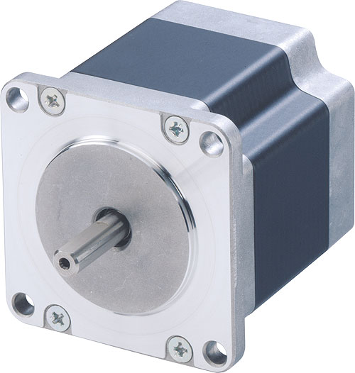
In the open-loop mode, conventional stepping motors control both speed and position accuracy extremely well. They are best for applications that require low speed, high holding brake force, and high torque. However, during high-speed operation, stepping motors typically generate excessive heat and make continuous operation impractical since it significantly shortens motor life. However, the demand for both high-speed and high-efficiency stepping motors has been steadily increasing, so the main sources of losses are significantly lowered by selecting uncommon laminated iron core material and improving the process of fastening the laminations.
Sorting out motion system losses
A typical motion system consists of a power supply, motor driver, motor, and a load. Although the power supply efficiency is not ideal and the load has mechanical losses, look at the driver and the motor to determine where most energy is lost.
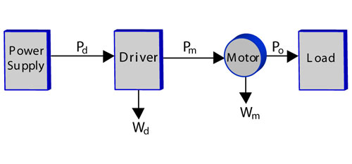
A typical drive system has multiple sources of electrical and mechanical losses that affect the overall system efficiency. “P” indicates the power applied to system components, and the “W” shows the energy lost due to component inefficiency.
The motor/drive total losses Wu, can be expressed as the difference between the power applied to the driver Pd, and the system output power Po applied to the load, Wu = Pd – Po. Driver losses Wd in turn, can be expressed as the difference between the power applied to the driver Pd, and the power that the driver applies to the motor, Pm, Wd = Pd – Pm . And motor losses, Wm, are the difference between the power applied to the motor, Pm, and the output power, Po, Wm = Pm – Po.
Percentage wise, the motor/driver losses in a holding mode are the worst, since no motion is applied to the load, Po = 0, but constant current flows through the driver and motor windings unless the power is removed. The holding-mode motor losses are relatively large compared with the driver losses.
The driver losses consist of inverter losses and losses in other components dissipating heat, and motor manufacturers can do little to reduce them. Motors have mechanical, electrical, and stray losses. Due to space limitations, this article reviews only electrical losses, which can be further divided into copper losses and iron losses. Copper losses come from the energy dissipated in copper wires of the motor stator windings.
Wires have certain resistance, so when current passes through them, a certain amount of energy is dissipated: W = I2 R. The copper losses of a multiple phase motor can be found easily based on current, resistance, and number of phases:
Wc = n I2 R
Where:
Wc = copper losses, W
n = number of phases
I = current, rms, A
R = winding resistance, Ohm
Wire resistance is inversely proportional to the wire cross-sectional area, S = π(d/2)2, and thus to wire diameter. One way to reduce resistance is to increase wire diameter, but since a certain number of turns is needed to create the required electromagnetic force, larger wire diameter would lead to larger motor size. So a compromise has to be found between heat dissipation and motor size.
The iron losses can be determined by simply subtracting the copper losses from the total motor losses:
Wfe = Wm – Wc.
Where:
Wm = total motor losses, W
Wfe = iron losses, W
The iron losses are generated by the flux change in the core caused by the rotation of the rotor (field) or a current change in the stator winding. Therefore, the iron losses can be divided into the iron losses caused by the field (called the field iron losses) and losses caused by the stator winding (called the stator winding iron losses). The two factors responsible for these losses are eddy currents and hysteresis.
Field iron losses
A hybrid-type stepping motor uses a permanent magnet rotor. The outer face of the rotor and the inner face of the stator have opposing inductive poles in the form of teeth. As the rotor teeth rotate relative to the stator teeth, the stator core flux changes resulting in the field iron losses. The following equation describes the field iron losses:
W0 = (2π/60) N T
Where:
W0 = field iron losses, W
N = motor speed, rpm
T = torque, N m

Typical stepping motor components are shaft and ball bearings, rotor sections 1 and 2 that contain a permanent magnet, and the stator with windings. Copper wires wound around the poles of the stator and the laminations used for stator construction have a direct impact on motor efficiency.
As mentioned above, field iron losses consist of eddy current losses and hysteresis losses, and each loss per unit of mass is expressed as:
We = ce Bm2 t2 k2 N2
Wh = ch Bm1.6 k N
Where:
We = eddy current losses, W/kg
Wh = hysteresis losses, W/kg
ce, = eddy current iron loss constant determined by material
ch = hysteresis iron loss constant determined by material
t = lamination sheet thickness, mm
k = constant determined by the number of pole pairs
Bm = flux density, T
N = motor speed, rpm

The maximum motor iron losses occur at about 1200 rpm. The stator winding iron losses decrease in the constant voltage area because the current is decreased. The field-iron losses steadily increase with speed and become the predominant factor at approximately 3000 rpm.
As seen from the equation above, eddy current losses are proportional to the square of the rotating speed, and hysteresis losses are directly proportional to the rotating speed.
Conventional stepping motor losses, winding current, and motor torque depend on motor speed. Although the driver attempts to maintain the current of a stepping motor at a constant value, it starts to decrease past 1000 rpm. This happens because as speed increases so does the motor impedance and at a certain speed, the voltage provided by the power supply becomes insufficient to maintain the constant current. The area of the current vs. rpm curve where the current decreases is called constant-voltage area. As the current decreases so do the copper losses.
The copper losses become insignificant at high speed, and because the motor losses are the sum of iron losses and copper losses, the motor losses become mostly due to the iron losses at approximately 3000 rpm. At high speed, iron losses of many conventional stepping motors exceed 90% of the total motor losses. That is why reducing iron losses of stepping motors intended for high-speed operation brings the greatest efficiency improvement.
Reducing iron losses
Several new magnetic core materials were developed over the last four decades, each with a higher magnetic field strength than the materials available before. Ferrite was one of the earliest magnetic materials used for building motor cores. Alnico magnets made available in the 1960s doubled the magnetic field strength. The rare-earth, high-energy magnets made of various grades of Samarium-Cobalt (SmCo) and Neodymium-Iron-Boron (NdFeB) magnetic materials were introduced in the 1970s.
However, motor cores made from stronger magnetic materials often can lead to higher losses associated with the core hysteresis and eddy currents. When examining the equations characterizing iron losses it becomes obvious that to lower these loses materials with low hysteresis constant ch, low eddy current constant ce, should be selected and the lamination thickness should be reduced.
The ability of a magnet to retain magnetization in response to a magnetizing force applied in both directions is normally presented in form of a plot called the hysteresis loop. Harder magnetic materials have a wider loop retaining a stronger field after the force is removed. Such materials have a greater hysteresis constant ch and produce greater losses when the direction of the force is reversed. Selecting a softer magnetic material with a smaller area inside the hysteresis loop, and thus a lower ch, reduces hysteresis losses.
Eddy currents are circular flow of electrons created on the surface of a conductor when it is exposed to an alternating magnetic field. Though this phenomenon has practical application in various devices, it is an unwanted effect in electric motors. Eddy currents waste energy through heat and create electromagnetic forces that oppose the main motor force. Using magnetic core materials with lower electrical conductivity is one option for reducing motor losses.
For example, silicon steel is an alloy of a low carbon steel and small amount of silicon, which has a relatively high volume resistivity. When used for building motor cores, it reduces the eddy current flow, and thus eddy current losses. Based on allowable losses per unit of weight, several grades are available. Each higher grade material costs more and has lower losses. Nickel alloys also have low losses, but cost considerably more and are difficult to process. Cobalt alloys have rather limited use due to still higher cost and even more difficult processing requirements.
Separating the core into thin laminations creates insulation barriers to eddy currents, which reduces the circulations to very small areas. Making the core laminations thinner also reduces eddy currents; however, it increases the core price. So, as the number of laminations in a given core increases, the eddy currents decrease. Note that the laminations must run perpendicular to the direction of the magnetic field.
When the core laminations are made, the insulation layer is placed around each lamination to keep the metal of the laminations from touching and creating an electrical path for eddy currents. Several types of insulation provide an insulation layer with different mechanical strengths. Oxide, varnish, enamel, and inorganic coatings trade impact resistance for process cost. The improved inorganic coating offers the best resistance and should be considered in high-performance applications.
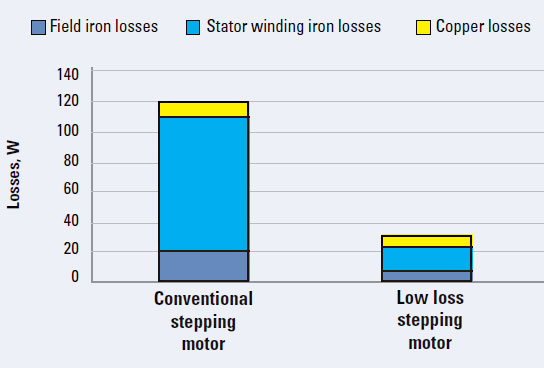
The low-loss motor’s copper losses slightly increase due to higher current. The stator-iron losses drop by approximately 80% while the field iron losses reduce approximately 70%. So, the overall motor losses are approximately 70% lower than the losses of a comparable conventional stepping motor.
Regardless of the insulation technique used, the method of stator-core lamination assembly should be carefully considered. When the laminations are fastened together to form a core, some assembly methods, such as riveting or welding, can break the insulation layer and create a path for eddy currents. This will increase motor eddy current losses. Low loss motor designs should pay special attention to the stator core stack and use fastening methods that leave the insulation layer intact.
Unfortunately, cores made of low eddy and hysteresis loss lamination materials often also have lower saturation flux density than cores made from conventional materials, which in turn, leads to lower torque. To boost torque, the current has to be increased, which leads to greater copper losses. So, when selecting the best lamination material, the required torque and both kinds of losses need to be considered.
A comparison of losses for various conventional and low-loss stepping motors is illustrated. A hypothetical conventional motor selected for this comparison measures 60 by 60 mm, has two phases and 50 pole pairs. The other specifications are 1.6 ohm resistance, 1.7A rated current, and 1.2 Nm maximum holding torque.
The low-loss motor has the same construction, except for the high-grade lamination material and the improved method of lamination assembly. Since using the high-grade lamination core results in lower torque compared to the conventional motor, a higher current was selected to equal the torque of both motors.
In addition to energy conservation and continuous running mode advantages, low-loss stepping motors offer another benefit. Positioning operations can run faster due to shorter cool-off times. A typical positioning operation cycle consists of acceleration time, rotation time, and hold (positioning) time. Such operation is called a trapezoidal drive. Dispensing mechanisms, assembly line, and inspection equipment are typical examples of such motion systems.
Quite often, the holding time – when the heat dissipation is the lowest – is used to cool the motor. Under such conditions, shortening the hold time can lead to motor overheating. However, if a low-loss motor is used, the heat dissipation is lower and so is the motor temperature. This allows shorter hold time and thus shorter overall cycle times.
Oriental Motor
www.orientalmotor.com
::Design World::
Filed Under: Motion control • motor controls, Motors • stepper

Tell Us What You Think!