by Tim Sparkman, Metal Injection Molding (MIM), Operations Manager, Dynacast
Metal injection molding can be made faster. Part of the process involves speeding the production of pre-sintered parts.
Metal Injection Molding (MIM) has proven its worth as a reliable way to make precision parts at high production volumes. MIM also offers plenty of design flexibility because it supports a variety of metal alloys, including various steels, Titanium, copper, nickel, and more. For all its advantages, though, MIM has traditionally had drawbacks related to productivity, part-to-part variation, and manufacturing costs.
Now a new approach to MIM dramatically increases productivity while reducing variation and costs. Developed by Dynacast, this process involves a rethinking of how to produce the green, or pre-sintered, parts.
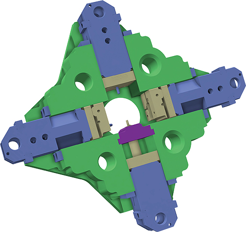
Traditional MIM uses modified injection molding machines from the plastics industry to produce the green part. A new MIM platform makes use of multi-slide tooling, which uses a set of sliders that converge in the die block to create the cores, cavity and runner system. Conventional MIM tools, by contrast, arrange the cores, cavities, and runners within two opposing mold halves.
Traditional MIM uses modified injection-molding machines to produce the green part. Likewise, MIM tooling is very much like the injection molds used for plastics.
Up to now, this approach has made sense. The mixture of metal powder and binder that form the green part flows enough like plastics that injection molding equipment and tooling work well with a few modifications to the machine’s barrel and injection screw. The tooling also requires runner changes and other modifications to work with MIM.
A shift from injection to die casting
The new MIM system gets rid of injection molding equipment and conventional tooling altogether. Instead, it takes its cues from precision die casting technology.
Engineers modified Dynacast’s proprietary A2 die-casting machine to make it compatible with MIM feedstocks. The modifications included the installation of a custom feeding system—a new hopper, gooseneck and feeding controls—optimized for the powder flow and thermal characteristics of MIM feedstocks.
In addition, the new MIM platform makes use of the company’s multi-slide tooling. Known in the die casting industry for its ability to produce precision components at high production volumes, this tooling uses a set of sliders that converge in the die block to create the cores, cavity and runner system. Conventional MIM tools arrange the cores, cavities and runners within two opposing mold halves.
Increased productivity
The A2 platform advantage is that it offers faster cycle times. The MIM system routinely produces green parts in 1.5 sec that would take 25 to 40 sec on a traditional MIM system. Thus, the cycle time advantage is such that it can often produce more parts-per-minute in a single cavity tool than traditional MIM can do on a multi-cavity tool. Multi-cavity configurations are available and enable even higher production rates.
The main reason for the A2’s cycle time edge is that the die casting-type feeding system eliminates the time required by a molding machine’s barrel and reciprocating screw to inject the MIM feedstock into the tool and recover for another shot.
Multi-slide tooling further enhances cycle times. A2 slides are smaller than traditional mold blocks and are pneumatically driven at high speeds. Slides also enable faster cooling rates because they dissipate heat efficiently through multiple die faces rather than the two massive mold faces found on conventional MIM tools.
Reduced variation, tighter tolerances
The consistency partly derives from the alignment offered by multi-slide tools. The registration of die faces measures 0.0015 in. TIR, versus as much as 0.005 in. with a typical MIM tool. The reduction in alignment errors, or “die mismatch,” reduces a source of dimensional variation that can carry through from the green part to the finished component.
Multi-slide tooling also helps keep part-to-part variation to a minimum compared to conventional multi-cavity injection molds. The reason why comes down to tooling size. Whether in single or multi-cavity configurations, multi-slide tools are more compact than comparable MIM tools. These smaller tools are less prone to parting line variation and its negative effect on the finished part’s dimensional tolerances.

The new MIM system routinely produces green parts in 1.5 sec that would take 25 to 40 sec on a traditional MIM system.
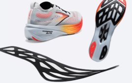
Through the tooling advantages and careful statistical process control, the new MIM achieves part-to-part consistency with tight dimensional tolerances. To take a recent example from a precision firearms component, it achieved a 1.67 Cpk on a key print tolerance of ±0.001 in., which translates to just one out-of-tolerance event per million parts.
Decreased defects
MIM has historically suffered from part defects, both visible and beneath the surface. Given all that has to go right, from a materials and processing standpoint as a part goes from molding to debinding to sintering, each step introduces the potential for part defects that can range from cosmetic to catastrophic.
A successful approach to tackling defect problems is by applying advanced process analysis and optimization techniques. Sink marks, which are rampant in MIM, represent a case in point. On two of the earliest of our MIM parts, sink marks were reduced by 99.9%. To achieve such a reduction, our engineers conducted experiments that evaluated every process factor that could affect sink, including gating, venting, temperatures, debinding, and sintering conditions. Thermal imaging cameras monitored the tool and the solidifying part. The work revealed, at least for these two components, that venting and gate thickness optimization would all but eliminate sink.
Lower tooling costs
Building a multi-slide tool requires less machining and assembly time than a comparable injection-molding tool. And unlike traditional MIM molds, multi-slide tools carry a guarantee for the life of the program, eliminating the cost of tooling rework and maintenance. Keep in mind that all MIM processes can require secondary tooling, which does add additional cost. Examples include setter plates for sintering or fixtures for machining.
Downstream of the green part production, the green parts from the A2 system go through the same debinding and sintering steps. They shrink at the same rate as other MIM parts, and they end up with a final density that typically exceeds 98%, just as it does with a well-controlled traditional MIM process.
In all regards related to mechanical and physical properties, the finished parts from this MIM process are equivalent to those of a traditional MIM process. The only difference is that those parts can now be more consistent and cost less to make.
Dynacast
www.dynacast.com
Filed Under: Molding • injection molding components, Die casting, Materials • advanced
Tell Us What You Think!