By Michael Jermann/ Assistant Editor
Spring Pins are used in many different assemblies for a variety of reasons: to serve as hinge pins and axles, to align components, or simply to fasten multiple components together. Spring Pins are formed by rolling and configuring a metal strip into a cylindrical shape that allows for radial compression and recovery. When properly implemented, Spring Pins provide reliable robust joints with excellent retention.
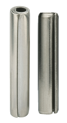
There are two types of Spring Pins: Coiled Pins (left) and Slotted Pins (right).
During installation, spring pins compress and conform to the smaller host hole. The compressed pin then exerts outward radial force against the hole wall. Retention is provided by compression and the resultant friction between the pin and hole wall. For this reason, surface area contact between the pin and the hole is critical.
Increasing radial stress and/or contact surface area can optimize retention. A larger, heavier pin will exhibit reduced flexibility and as a result, the installed spring load or radial stress will be higher. Coiled spring pins are the exception to this rule as they are available in multiple duties (light, standard and heavy) to provide a greater range of strength and flexibility within a given diameter.
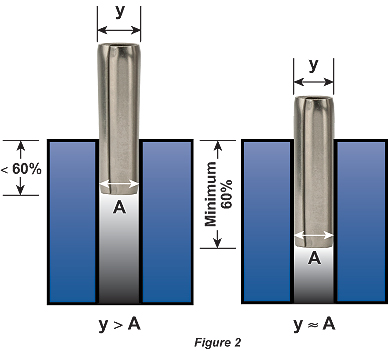
The example on the left shows how the protruding end of the pin maintains a diameter larger than the hole when less than 60% of the length is retained in the host hole. On the right, the protruding end of the pin has a diameter approximately equal to the hole.
There is a linear relationship between friction/retention and the engagement length of a spring pin within a hole. Therefore, increasing the length of the pin and the resulting contact surface area between the pin and host hole will result in higher retention. Since there is no retention at the very end of the pin due to the chamfer, it is important to take the chamfer length into consideration when calculating engagement length. At no point should the pin’s chamfer be located in the shear plane between mating holes, as this can lead to translation of tangential force into axial force that can contribute to “walking” or pin movement away from the shear plane until the force is neutralized. To avoid this scenario, it is recommended that the end of the pin clear the shear plane by one pin diameter or more. This condition can also be caused by tapered holes that can similarly translate tangential force into outward movement. As such, it is recommended that holes with no taper be implemented and if taper is necessary it remain under 1° included.
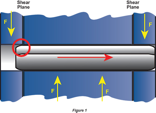
The pin’s chamfer must not be in the shear plane. In this case, the pin will move in the direction indicated until the chamfer is no longer in the shear plane.
Spring Pins will recover a portion of their pre-installed diameter wherever they are unsupported by the host material. In applications for alignment, the spring pin should be inserted 60% of the total pin length into the initial hole to permanently fix its position and control the diameter of the protruding end. In free-fit hinge applications, the pin should stay in the outer members provided the width of each of these locations is greater than or equal to 1.5x the pin’s diameter. If this guideline is not satisfied, retaining the pin in the center component may be prudent. Friction fit hinges require all hinge components be prepared with matched holes and that each component, regardless of the number of hinge segments, maximizes engagement with the pin.
Spirol
www.spirol.com
Filed Under: MOTION CONTROL, MORE INDUSTRIES


how do you calculate the pressure generated due to expansion of pin